
Help with a wiring circuit
 06-03-2015, 04:49 AM
#1
Addict
Rennlist Member
Rennlist Member
Thread Starter
I was wondering if some of the more knowledgable electronics people could assist with this question. I am looking at adding a for more modern features, it is for a variety of reasons but in this case, if I can use the late model steering column from the 991 where this switch is from I can get the steering wheel which i like and is a better shape and size than the original,
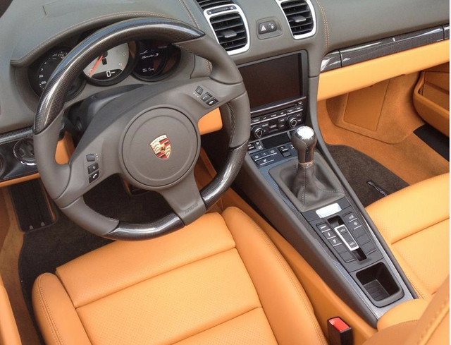
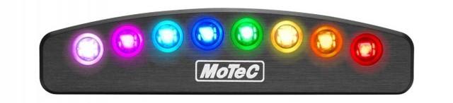
the combination switch also has an integrated steering angle sensor which I will need one way or another. Also the steering wheel has two other good options, it will allow me to fit the Motec SLM shift lights where Porsche fits the PDK Launch control display.
Also stereo and phone controls will then integrate with the Alpine ILX-700.
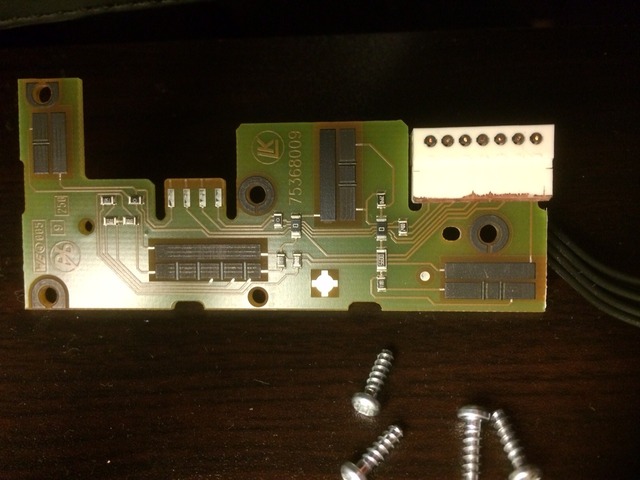
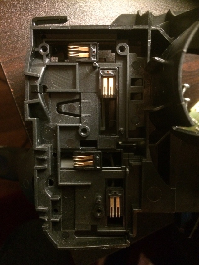
As you can see the spring loaded contacts that slide in tracks against the board. As mentioned the washer jet circuit is conventional. If you look at the circuit board you will see three contacts that is where a plug clips onto the board. These wires goes to the wiper switch and do the amount of time delay on the intermittent circuit. These are the 3 wires on the left, the right 4th circuit contact doesn't have a wire attached despite the plug having a place to run that 4th wire. One of the plugs is still on the board at the top right. This board does both the wipers and on board computer. The wiper part is to the left and the computer part is to the right.
The indicators which are on the other side of this combination switch seems to work conventionally, I can put the multimeter on the outputs and get continuity. I get continuity with the washer circuit but not the wiper speed circuit. I also can't figure the wiper intermittent circuit, it has three levels of time delay. I tested the computer stalk and couldn't get any continuity. There is a chance I am not testing the circuit correctly. I am not using any current to test.
Basically I am testing the wires which attach to the board before it goes into the Can Bus processor. I hope to convert the wiring in the car much like what Carl has done with his car. I don't see the integration of the wheel and the column as I big issue as I have a plan for for. I would also like to use keyless go which can be done with the late model columns as they lock the steering with a module on the column
the combination switch also has an integrated steering angle sensor which I will need one way or another. Also the steering wheel has two other good options, it will allow me to fit the Motec SLM shift lights where Porsche fits the PDK Launch control display.
Also stereo and phone controls will then integrate with the Alpine ILX-700.
As you can see the spring loaded contacts that slide in tracks against the board. As mentioned the washer jet circuit is conventional. If you look at the circuit board you will see three contacts that is where a plug clips onto the board. These wires goes to the wiper switch and do the amount of time delay on the intermittent circuit. These are the 3 wires on the left, the right 4th circuit contact doesn't have a wire attached despite the plug having a place to run that 4th wire. One of the plugs is still on the board at the top right. This board does both the wipers and on board computer. The wiper part is to the left and the computer part is to the right.
The indicators which are on the other side of this combination switch seems to work conventionally, I can put the multimeter on the outputs and get continuity. I get continuity with the washer circuit but not the wiper speed circuit. I also can't figure the wiper intermittent circuit, it has three levels of time delay. I tested the computer stalk and couldn't get any continuity. There is a chance I am not testing the circuit correctly. I am not using any current to test.
Basically I am testing the wires which attach to the board before it goes into the Can Bus processor. I hope to convert the wiring in the car much like what Carl has done with his car. I don't see the integration of the wheel and the column as I big issue as I have a plan for for. I would also like to use keyless go which can be done with the late model columns as they lock the steering with a module on the column
 06-03-2015, 04:56 AM
#2
Archive Gatekeeper
Rennlist Member
Rennlist Member
There isn't a single question mark in your post. What's the question? 
06-03-2015, 05:57 AM
#3
Addict
Rennlist Member
Rennlist Member
Thread Starter
 Is this a conventional or a special Can Bus circuit?
06-04-2015, 09:10 AM
Is this a conventional or a special Can Bus circuit?
06-04-2015, 09:10 AM
#5
Rennlist Member
While I am not an electronic expert, that circuit board looks like a low-voltage (3V, 4.5V or 5.4V) setup. The wiper speeds are most likely PWM signals to control wiper speed. I believe most modern cars control them that way.
Have you had a look at the wiper motor? If so, how many connections does it have?
Cheers!
Carl
Have you had a look at the wiper motor? If so, how many connections does it have?
Cheers!
Carl
06-04-2015, 10:40 AM
#6
Nordschleife Master
Join Date: Dec 2004
Location: Guelph, Ontario, Canada
Posts: 6,164
Likes: 0
Received 5 Likes
on
5 Posts
The steering wheel likely is connected just to the CANBUS. So a power wire, ground wire, CANBUS wire and maybe airbag trigger wire.
Those chips are likely the serial control for CANBUS .
Not an Electrical engineer, though.
Those chips are likely the serial control for CANBUS .
Not an Electrical engineer, though.
Trending Topics
06-04-2015, 12:15 PM
#8
Electron Wrangler
Lifetime Rennlist
Member
Lifetime Rennlist
Member
I suspect this is all low voltage switch processing/control and that there is a module elsewhere that drives the circuits directly - e.g. closer to the wiper motor etc, possibly connected by CANbus - I'd investigate that on the source vehicle.
Be warned that poking around testing like this could destroy the very circuits you are trying to test... I'd stop going down this path any try to deduce operation first from documentation.
Alan
Be warned that poking around testing like this could destroy the very circuits you are trying to test... I'd stop going down this path any try to deduce operation first from documentation.
Alan
06-04-2015, 03:38 PM
#9
Addict
Rennlist Member
Rennlist Member
Thread Starter
Thanks for the responses guys, it will be hard to get anymore info as Porsche keeps this online to their dealerships only. The car is obviously very new and their will be limited knowledge about it. Although the 997 is basically working in exactly the same manner.
Alan I hope haven't damaged anything, I was only using a multimeter with no external voltage applied, can this cause damage? I will sell the switch if it is a hopeless cause but I wouldn't sell it if there is cause for concern. Thanks again
Alan I hope haven't damaged anything, I was only using a multimeter with no external voltage applied, can this cause damage? I will sell the switch if it is a hopeless cause but I wouldn't sell it if there is cause for concern. Thanks again
06-04-2015, 03:50 PM
#10
Rennlist Member
Chances of causing damage with a meter are slim.
Since this is likely a digital bus of some kind you might have to use something like an Arduino to process the inputs and control the 928 systems via relays attached to Arduino outputs.
Since this is likely a digital bus of some kind you might have to use something like an Arduino to process the inputs and control the 928 systems via relays attached to Arduino outputs.
06-04-2015, 11:59 PM
#11
Instructor

Join Date: Jun 2009
Location: gone to Pelican - search for reanimotion
Posts: 220
Likes: 0
Received 1 Like
on
1 Post
the contacts are providing a resistive signal via the little surface mount chips (resistors) and define the lever position on one wire to the controller via a changing resistance depending on position (push/pull on one and up/down on the other) i.e. position A goes through one resistor and position B passes through two
I have the VW/Audi/VAG and 997 switch units here and am slowly integrating the same thing but with a 997 PDK wheel via a hybrid steering shaft etc.
I'm going to assume the 991 is the same at least in concept.
The main controller module that plugs in behind is the interpreter of these signals and then translates to the CAN-bus for the rest of the vehicle.
LIN single wire comms is the usual method between the Switch/Controller and the multi function wheel buttons
It will depend on if you want to integrate the 991 controller or just the switch units. Reverse engineering the canbus to the oem controller is painful but not impossible, replacing it with a programmable controller would be a simpler option given the resistive switching.
Something like the OBR PCM2 or Motec PDM maybe even the Pectel ecu could do it via analog channels and CAN outputs, otherwise a number of custom options are available.
Last edited by svpmx83; 06-05-2015 at 03:30 AM.
06-05-2015, 12:36 AM
#12
Instructor
Join Date: Jun 2009
Location: gone to Pelican - search for reanimotion
Posts: 220
Likes: 0
Received 1 Like
on
1 Post
Well the circuit doesn't seem to test in a conventional matter, why can't I get continuity? Am I making an error in testing? I don't understand these little looking chips on the board, are they effecting the results? What are these chips for may be a way of asking the same question to get an answer. Is this a conventional or a special Can Bus circuit?
Is this a conventional or a special Can Bus circuit?They are resistors, the ones with 0 on the face are zero ohms and being used as bridges for the single sided circuit board