When you click on links to various merchants on this site and make a purchase, this can result in this site earning a commission. Affiliate programs and affiliations include, but are not limited to, the eBay Partner Network.
Hope everyone had a nice memorial day weekend. We had terrific weather here although our little seaside community is in uproar over the Plains All American oil spill. I live right on the coast, about 6-7 miles south-east of the spill and when the wind is just right ... we have a noxious funk outside. Not to mention the beaches just west of our home are closed off. Very upsetting to say the least. Our coastline here is truly pristine - abundant wildlife and very good surfing. To have some POS company with what we're finding out to be a terrible safety record allow this to happen here is infuriating.
Anyhow, onto something more pleasant. Had a few hours here and there over the last few days and its been filled with cleaning, cleaning and more cleaning. I took off the spark plug harness and fan assembly for cleaning and testing continuity and found the below:
- Power steering fluid is caked all over the drivers side of the engine. I think the PO overfilled the reservoir as the hoses look good and there doesn't appear to be an active leak.
- Looking at an oil trail from near the belt tensioner, I think the tensioner has leaked out completely. So that's going to be rebuilt when I get there.
- Took my drilled out flappy spindle to a local welding shop. The shop carefully welded up the hole I over-drilled and re-tapped it. One hour and $80 later the spindle looks like new and threads work great - like nothing ever happened!
Throttle body testing:
I built up the test rig in the picture attached below. I cut some extra thick plexi-glass in a rough outline of the intake inlets and used extra large washers on the bolts/nuts so as to form a decent seal. Note that cutting plexiglass with a jig saw causes the blade to get hot and melt the glass . Use a coarse blade and go fast to avoid melting.
I then plugged up all holes/hoses with plugs and started pumping up pressure.
Using soapy water I found leaks on virtually all the joints at the rubber boot for the MAF and all the hoses to the ISV. Via tightening and adding clamps (some clamps were actually missing) I was able to stop leaks all hosed connections.
Then I found the real culprit - the throttle valve bearing! Blowing bubbles everywhere! Looks like this apparatus is coming apart next.
I'm very glad I decided to do this testing with the throttle body out of the car. I can't imagine trying this pressure testing with the body installed.
I suspect most of our throttle body bushings will be leaking to some extent by now given it is not something most can or will test. Presumably the difficult bit is to know the point at which leakage is no longer tolerable.
I try to assess this in Sharktuner by taking a squint at where the ISV is positioned on the basis that if the ISV is operating at or near 55% any notional leakage is acceptable. If the ISV is having to nip in to control idle rpm's that would suggest [I think] that excessive leaks were in play & thus time to pull the inlet manifold.
I suspect most of our throttle body bushings will be leaking to some extent by now given it is not something most can or will test. Presumably the difficult bit is to know the point at which leakage is no longer tolerable.
The bearings for the throttle butterfly are well established as a leak point - they're the same type of bearing as the ones on the flappy, with an integral tiny little rubber lip seal.
Replacing them should be on anyone's list when replacing all the rubber bits on the intake.
Got my injectors back from the cleaners today. Looks like they were in fair shape - now looking pretty good according to the test results. Nice not having to replace any of these
Had to add a few more parts to my order from Roger (a cracked air hose and some more bearings) - hopefully that shipment will be arriving tomorrow.
Typical results- not difficult to see why you might lose 3% or so power delivery. If you can still discern which injector is which you can try positioning them with the higher flowing units on cylinders 6,2, 7 & 3 in that order.
The inner cylinders are fed by the longer runners and seem to fill better but get the same fuel as the other cylinders. Frankly I doubt you would feel any difference but fine tuning is all about getting as many of these marginal items optimal.
The injectors are nicely labeled so I'll install as you say. My motivation for the cleaning was to systemically eliminate any/all potential causes for poor performance. I thought about testing/cleaning them myself, but, why not have the pros do it since the cost was reasonable ($180 for all 8).
The new fuel lines are coming in today so I'm thinking through what its going to take to install them - FYI they're the 'Lifetime' lines from Greg, and, after reading through some of the threads on the subject, the recommendation is "tight but not too tight" when installing. Not sure what to make of that recommendation LOL.
Jumping the fuel pump and testing for leaks is what has to be done regardless - but, I'd prefer to have a test that doesn't require my nose/fingers as the sampling system. I'm curious if there's a way to test for leaks using a vacuum pump and air?
Doubtless the fuel lines will be a good investment and top of the integrity importance list with the TB/WP.
You could rig an air test circuit by disconnecting at the fuel pump discharge [adapt as a pressuring port] and at the pressure regulator outlet port [that would need closing off]. The inlet manifold can remain off the car but the injectors would have to be on the fuel rails- they should hold tight. You would need a pressure gauge in the circuit and can test at the fuel rail pressure of 3 barg. Look for air leaks with soapy water spray. Just ensure the inlet runners are bunged/sealed.
I have never done this but do not see any problems doing so. The back pressure control valve should remain closed until the pressure reaches the set point so you can also test for this. If you use the pressure pump port of the Mityvac pump your hands will get very tired- better to use a tyre air compressor- just be careful not to over pressure the system.
Hi all,
I managed to replace the throttle plate bearings without much pain. I'm getting pretty handy with drilling via the dremel. I assembled the throttle body an no leaks!
Can someone confirm the throttle plate spring assembly below? I took it apart assuming it would be identical to Dwayne'so write up (hence I didn't take good photos) but upon reassembly it was different.
It works like it did prior, but I'm not sure if it was correct in the first place.
Although I only had a couple of hours on Saturday, I managed to get a few items checked off the to-do list. Late last week I received all the lifetime fuel lines from Roger and they looked quite good - really nice actually. I'm now convinced this was money well spent.
After inspecting the construction (and instructions) from Greg I have to commend Greg for these fuel lines! Installing them left me with a solid sense of safety/quality - especially when compared with the old lines as the old lines appear woefully inadequate. The rear "u-line" was in fact cracked!
My only issue hesitation per the fuel lines is originality - I want a 100% original car (I keep all my cars as original as possible) ... so I guess I have compromised , but, this is an area I can justify it!
- Replaced the crank position sensor. That little bugger was tough to get out! The plastic was completely brittle/melted (glad I replaced it!) and I had to drill a hole so has to get a screw into the top so I could get some leverage to pry it out.
I took apart the passenger's side timing belt cover for further inspection and it looks like the cam gears are worn. Not sure as to the extent of the wear, but, I'm seeing some sparkle on the inside of the cam covers. Is this most likely aluminum being worn off the gears?
Typical wear pattern-doubtless worse on the 5/8 bank than the 1/4 bank? There are different views as to when the wheels should be considered as being at end of life. The top flats tend to go first but interestingly I have never seen the indents polishing- this I find a little strange given they are supposed to take the shear load. The theory is that once the coating goes the aluminium underneath will go quickly.
Given all you are doing it is probably prudent to pull the cam wheels and have them re-coated assuming they are suitable candidates. Colin [Lizard 928] can arrange this for you- quite possibly others can as well. There is debate about the effectiveness of this approach- I have no position on this but have a pair of recoated wheels to try in due course. If they work as good as they look I will be delighted. New ones are many $$$.
I am losing track of what you have done so far- have you done the TB/WP yet?
Rgds
Fred
Hi Fred,
That was a photo of the passenger's side cam gear as I just opened it up for the first time. Since I have a bit of time before the intake/cam covers come back from powder coating (maybe another 2 weeks), I'm inspecting and cleaning. I haven't completed any of the intake/TB water pump jobs yet
Coating seems like a good option at this point since the wear doesn't appear too bad.

 05-22-2015, 09:50 AM


 . Use a coarse blade and go fast to avoid melting.
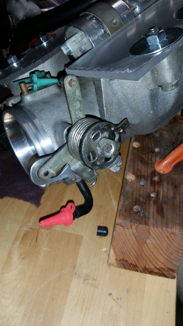

 , but, this is an area I can justify it!