When you click on links to various merchants on this site and make a purchase, this can result in this site earning a commission. Affiliate programs and affiliations include, but are not limited to, the eBay Partner Network.
Now it's snowing..! LOL...
Snowing quite hard here, and sticking.
A few days ago, we had a big ice storm.
Truly weather roulette around here.
Probably see a rainbow later today...
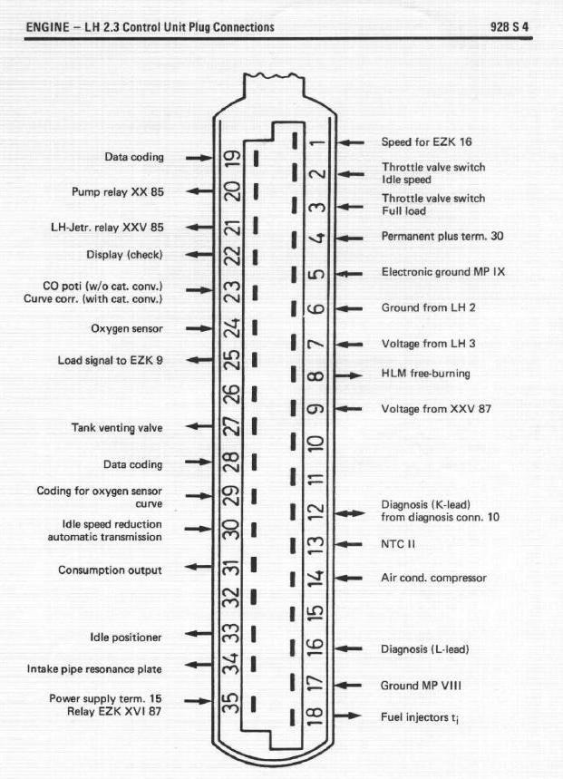
So, I got like 3 ohms with the injector harness connected to its ground point (VIII). I realized i did not connect the wounded wire to its ground point (IX)so I did and checked my readings again. Now the ohms are like 165! From reading other thread from Rich9928p I should be looking for a cut wire or a problem at MP VII. MP VII is the ground strap connection.
i. Power and Ground connections are key points to inspect and clean. The LH is grounded via Pin 17 to chassis ground point VIII. Use an Ohm meter to measure the resistance between LH connector Pin 17 and a chassis ground point. It should read as close to zero as possible. If it reads a high resistance, a corroded ground connection at MP VII or cut in the wire could be the problem.
Electrical stuff is not my forte and I am easily confused.
According to this picture the 'hook end' of the connector should be next to pin 1. On the connector on my 88 the 'hook end' of the connector is near pin 18.
I looked at the 90 GT in my garage and it too had the same orientation.
I confirmed constant 12 volts at pin 4 and near 0.3 ohms at pin 17. That would indicate the grounds are fine and 12 volts is being provided.
I can't reconcile the difference in the connector styles. I got that picture from a thread about '88 pinouts I think was provided by Andrew.
The grounds can test with no resistance with a meter, but have insufficient capacity to sustain the volume of current, ie, number of electrons, to operate the car. On top of that, a ground failure can appear random because presumably humidity or mechanical disturbance will make the passing of sufficient current variable. It is very misleading when narrowing issues. That's why we clean all the grounds, polish and re-fuse the CE panel, and replace the ground strap on these old things before even trying to start them.
Just a reminder that Ohm readings need to be taken with the battery disconnected, particularly when checking grounds and primary wiring. A wire with resistance will have a voltage drop through it when any current is flowing. Amazingly, Ohm meters pass a small current through the part or connection you are testing, and that can easily mess up your readings if there's more than zero Ohms.
Just a reminder that Ohm readings need to be taken with the battery disconnected, particularly when checking grounds and primary wiring. A wire with resistance will have a voltage drop through it when any current is flowing. Amazingly, Ohm meters pass a small current through the part or connection you are testing, and that can easily mess up your readings if there's more than zero Ohms.
Hope this helps!
Wow - I did not know that - and it confirms my lack of knowledge. Thanks!
I rechecked my readings with the battery disconnected. 0.00 ohms at pins 17 and 5.
Pin 6 to chassis I get no reading at all. Above it says I am supposed to get less than .50 ohms
Last edited by Kevin in Atlanta; 02-21-2015 at 11:06 AM.
Reason: Added Pin #6
an easy check to ensure your meter is functioning correctly is set the selector to resistance/ohms and touch the negative and positive leads together..........the meter should read zero and depending on model may also beep.
Separating the leads should give a max reading or no readout on the meter.


 02-18-2015, 02:47 PM