
GTS reverse gear B3 clutch replacement DIY
 01-16-2015, 07:40 AM
#1
Rennlist Member
Thread Starter
Found the time to translate the tutorial into English, have fun! 
MB automatic (722.3), repair of reverse (clutch B3)
This is a direct translation of my last tutorial in the German Porsche forum PFF. I have to admit that I ran it through different translators and spell checkers, just to save some time. Fixed most errors, but I�m sure the instructions are not perfect, sorry. But I think they are understandable and should help you guys to fix a similar problem.
I have done the repairs described here on my GTS, but the tutorial is valid for all 4-speed automatics. The basic principle of the 3-speed automatic is the same, but the components inside are slightly different. Reverse gear is activated by a brake band (B3) in the 3-speed automatics. To seal the primary pump is nearly identical (actually easier, because there is no B3 piston).
Unfortunately, this guide when it comes to the repair of clutches and brake bands, is only applicable the MB 722.3.
Fault diagnosis or fault pattern
The automatic transmissions in our 928 are all manufactured by Mercedes Benz and very robust (with regular maintenance). The first thing that refuses to work (almost always) is the reverse. The typical symptoms are:
1. After reverse gear is selected, it will take longer and longer until it engages. There is a noticeable time delay from �P� to �R� or any time �R� is selected. Finally B3 will no longer engage at all or the clutch will slip.
2. A hissing sound is heard when "R" is selected. This is due to a partial defective inner rubber lip seal on piston B3. The seal leaves the machined surface inside the primary pump housing. The lip seal is damaged and it will no longer seal 100%. The sound is generated by ATF fluid leaking by the seal.
3. The other indicator is a slightly "grinding" or "rattling" sound while reversing. Piston B3 touches the outer casing of clutch K1. This will leave grinding marks inside piston B3. Do not confuse this with the normal noise while reversing. The high gear ratio of reverse produces noise, similar to a manual reversing but fainter, this is normal. If unsure, listen to another vehicle. No need to find another 928 with a four speed automatic any Mercedes with a 722.3 will do .
Do not drive with a noisy reverse gear for too long (even if the MB diagnostic manual says something else). The piston extends further and further up to the point where there is internal damage. Plus metal shavings in the ATF circuit are not really good.
Planned Procedure (ideal winter project because it takes a lot of time)
Replacement of the inner friction discs B3 and measure the play from the primary pump housing to piston B3. Examination of the clutch K1 (wear check). Replacement of all accessible O-rings (lid of the pistons and various other components). Renewal of the lip seals on piston B3 and complete seal job on the primary pump.
Preparation
Jack up the vehicle high enough to be able to remove the rear axle and tranny, or (even better) use a lift.
The following items must be removed to get to the Rogerbox
Exhaust System: pre- and final mufflers of the exhaust are sufficient. Heat shields above those also have to be removed too. Cats can stay attached to the manifold.
The rear axle must also be completely removed. Sounds complicated, but it is not.
Before you start however, make sure that the transmission is secured to the upper part of the rear sway bar with a chain! (Photo)
Remove emergency brake cable from handle inside the vehicle. Remove all six shock absorber nuts inside the trunk. Remove toe eccentric bolts completely (mark their positions with some paint before removal). Disconnect the brake wear indicator plugs at the rear axle. Unbolt the brake calipers (brake lines remain connected) and hang them down on some wire. Remove the spare wheel in the trunk and disconnect both (left and right) RDK, PSD and brake wear indicator plug holders. Once disconnected, push them through to the outside. Remove the CV-joint bolts on both sides of the differential housing.
Remove the stabilizer coupling rod.
Now support the rear axle in the middle with a big hydraulic jack.
Finally eight bolts are left, six connect the cross member to the body and two are attached to the tranny mounts.
Automatic removal
Drain ATF completely (oil pan and torque converter) and remove oil lines.
Bowden cable (control pressure)
Detach the control pressure cable at the engine. Twist and remove the round plastic housing at the tranny as well. Disconnect the bowden cable at the tranny too.
Kickdown solenoid
Remove the round plug on the kickdown solenoid.
Vacuum modulator
Disconnect hose on the vacuum modulator.
Gear selector linkage
Disconnect the gear selector cable at the tranny and remove the two alan bolts of the mount.
Slave cylinder (PSD)
Remove all related supports for the PSD hydraulic line. Unscrew PSD slave-cylinder bolts.
Lowering of automatic with a suitable transmission jack.
Loosen and remove the rear clamp bolt. Remove the four bolts that attach the torque tube to the bell housing. The upper bolts are a little tricky there is not a lot of room available. You will need multiple extensions and one universal joint behind the 19 mm socket. On the top of the bell housing you will find one small M6 bolt for the gear selector guide tube, remove it too. Transmission can gently be pushed back now until the rear clamp detaches from the drive shaft of the TT.
The transmission can be completely lowered as a unit now.
Repair of automatic
IMPORTANT: Place the automatic only on a suitable, stable surface! I used my hydraulic engine crane with balancer, works great to maneuver the automatic into the correct position. The Rogerbox has to be tilted later as far as possible into the vertical to measure the clearance between piston B3 and the reverse clutch package.
Elevate the automatic a little, use wooden blocks to support the bell housing and the differential. Drain the gear oil from the differential and recover (can be reused). If you forget this step, it will run out of the oil breather when the tranny is tilted into the vertical later.
Removal of the torque converter
Remove the three rubber plugs on the front bell housing. There are a total of six screws visible; they attach the rear flexplate to the torque converter. Loosen but do not remove them yet. Remove the bell housing alan bolts and remove the front carefully with converter as a unit. Remove the torque converter bolts from the flexplate now. Removal of the torque converter from the flexplate requires a little patience (dead blow hammer and a suitable extension).
Tip: If the automatic has never been touched so far, I highly recommend replacing the torque converter carrier bearings. These are not expensive and you will not have an easier time again to access them. My bearings gave up at 170,000 km They have only seen 63,000 km since and I left them untouched. . When I replaced my torque converter bearings, I also replaced the torque tube with a 928Intl in 2005. But this is optional.
Removing the primary pump with piston B3
After the torque converter has been removed, you have direct access to the primary pump. Remove all bolts and hand tighten two M8 bolts into the existing threads. Pull the pump gently toward you. Once the pump housing is removed, clutch K1 and brake band B1 are visible. Place a large amount of paper towels below the bell housing because some ATF will leak out.
Clutch K1 and brake band B1
First, remove the brake band B1 (note installation position). Remove the safety switch (36 mm socket) and remove the valve behind it. This step is enough to take the brake band out. However, the O-ring of the piston cover B1 will be replaced, therefore it must be removed too. The lid is secured with a retaining clip. To remove the clip, the round lid has to be pushed in a little. The spring tension of piston B1 is quite high and you need a suitable, large wood clamp (see photo). Release tension completely, when the clip is removed, carefully remove the piston (check the Teflon seal). Finally remove the B1 brake band plastic guide through the now empty opening too.
K1
Now take out the complete clutch package towards the front. After removal you should have good access to the disks of reverse clutch B3. Tip: make sure that the you secure the needle bearing with their spacers in the center of K1.
Clutch discs removal B3
The discs of B3 for the reverse gear can be taken out easily with a magnet (photo). Observe the order and position of the inner and outer plates and do not confuse them. Now it is easy to check the wear of the clutch. All my outer metal discs looked like new, no scratches, nearly no wear. The inner discs however with the friction material were a completely different story. Nearly down to the bare metal, all four had only a 0.9 mm left. The new friction discs from my friendly MB dealer had 2.1 mm. This means that piston B3 had to compensate 4.8 mm of total wear. No wonder that reverse gear engagement took a very long time and B3 touched K1. I was certainly only days away from total reverse failure! Latest when piston B3 pushes only against the housing of K1 and no pressure is applied to clutch B3�. It�s all over! B3 slips and the car moves only forward.
Sealing of all remaining components
Cover of the piston B2
Lightly press the cover in with the screw clamp and remove the snap ring. This one is easy, there is not a lot of pressure from piston B2. The lid sits very tightly in the bore and likes to resist extraction. Work out the cover with needle nose pliers. After the lid is removed, the O-ring, which will be replaced is visible.
IMPORTANT !!! Do not try pull out piston B2, unless you are planning on a complete automatic overhaul job! It could happen that the little thrust pin inside of brake band B2 falls out! B2 is completely ineffective without the pin! You will realize this after assembly quite fast, because your car will only drive backwards!
Remove and replace O-ring. I always cover the contact surface of the O-ring with a little Vaseline, with this it remains in position and the lid slides better into position without bending. Insert the cover nice and plain and secure it with the snap again.
IMPORTANT !!! Make sure that the cover rests evenly all around the retainer clip! Again, needle-nose pliers are very helpful. If the lid is slightly tilted, nothing happens (function of the piston B2). But it may happen that there will be leaks. The contact surface of the O-ring to the cover is not very large.
Governor cover seal
Basically the same as cover B2, only you do not need clamps. It�s just a cover. Remove the retaining ring, remove the cover and replace O-ring behind it. When inserting the lid also lubricate the O-ring with Vaseline and make sure that the cover is pushing flush against the circlip.
Gear selector lever shaft seal
This is a little more extensive, but not very difficult. First, remove the filter by removing the three Phillips screws. On the outside, the selector lever is held on the shaft with a single bolt with nut (M6). Once the bolt is out you have access to the electrical gear selector indicator switch (2x M6). Untighten the two bolts and remove the switch.
Now move to the inside. The individual gears are locked in position by a metal spring with roller (M6 with 10 mm socket wrench). Unbolt and take the whole spring unit out. A single alan bolt secures (photo) the axis onto the lever. The alan bolt has to be removed, now the shaft can be pulled to the outside.
Remove the old shaft seal with a suitable tool and coat the new oil seal with ATF. Drive it in with a socket until it sits flush in the opening. The rest is assembly in reverse order.
Protection switch and valve
Loosen and unscrew the switch with a 36 mm socket wrench. At the end of the switch you will find an O-ring, replace and lubricate it with some ATF. Inside you�ll find the actual valve, remove and replace the two O-rings. Coat the new O-rings with some ATF. When you insert the valve, make sure that the thrust pin sits securely in brake band B1. Tightening torque: 70 NM (M27 x 1.5 thread).
Vacuum modulator
The modulator is kept in position with two alan screws, remove them and remove the retaining plate. Pull the modulator out. Replace O-ring lubricate it with some ATF and install the modulator again with the piston. The rubber cap which covers the small "T-Handle" can be replaced too, to prevent vacuum leaks. The cap is available as an individual part at MB.
Kickdown solenoid
Loosen the bolt and unscrew completely. On the metal part of the valve you�ll find three O-rings replace them. Also replace the aluminum washer which seals the black kickdown housing against the automatic. Tightening torque of 20 NM M14 x 1.5 thread.
Breather on top of the automatic
In most cases, the plastic part is not critical and does not tend to leak ATF. But after twenty years plus the O-ring has certainly hardened. Recommendation: Replace the entire air vent, because the breather usually breaks when disassembly is attempted. Pry out the black plastic part on top and remove the brighter inner part carefully. If a plastic part remains in the opening it can be easily removed with a vacuum cleaner. The new vent is simply pressed and clicked into position. Also wet the O-ring again with some ATF before installation.
Replacement of the seal behind the cover of the secondary pump (if installed)
I have not touched this part on my GTS, since the large gasket is not made of rubber behind the cover. The cover is completely dry in my GTS. The replacement of the seal is however quite easy if necessary. Hold the adjusting screw with a screwdriver and loosen and remove the counter lock nut. Do not turn the adjuster; this will change the hydraulic pressure. Now unbolt the three alan screws, the cover can be removed now. Reassembly in reverse order. Tightening torque of the alan screws M6 8 NM and the lock nut M6, 6 NM.
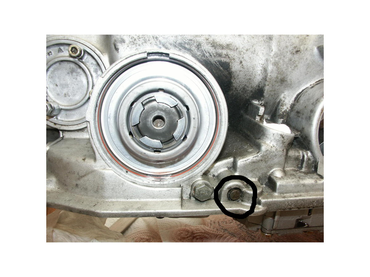
Primary pump and piston B3
Actuator piston B3 and the primary pump are integrated in one housing. The whole thing is extremely sturdy and it does not have the tendency to create problems. Leaks usually occur from hardened O-rings and seals. In order to separate the primary pump from the housing and remove it, it is necessary to extract piston B3. The piston sits on the backside and is secured with a locking ring, pressure plate and a handful of steel springs. The snap ring can be removed with a DIY tool without much effort (photo). I used a 75 mm PVC pipe connector. Available at many hardware stores in the plumbing department. Cut out two round openings, big enough to access the snap ring which has to be removed. I used my 12 ton shop press. With a little skill, you can achieve the same result with a standard vise. If the piston is removed, you have access to M8 bolts. They secure the primary pump in position. After removal of the bolts, the pump can be removed and the O-ring may be replaced. The torque converter shaft seal can be easily replaced too now. Before placement of the the primary pump into the housing: clean the 8 mm screws of the primary pump and its threads and degrease thoroughly with some brake cleaner. Lubricate the new O-ring with some ATF. Coat the bolts with some non-hardening sealant (I used Hylomar). Tightening torque of the primary pump bolts: 20 NM.
Also replace the lip seals of piston B3. Often the inner sleeve is torn and needs to be replaced. Note the installation position of the sleeve! The hydraulic pressure seals the piston sleeve against the housing (principle of a bicycle pump). The rebuilt of the B3 piston in the housing is not difficult, but requires some attention to detail. Shortly before the piston lip seal disappears, make absolutely sure that the large outer seal is entering the housing without being pinched. I used a wooden toothpick to ensure the correct installation position and to prevent damage (photo). Do not use any sharp objects!
The small inner sleeve in the center of the piston is more difficult. I initially had some problems with the inner sleeve, it did not cooperate. Important! Do not try to press it down! The sealing lip can be damaged quickly!
If the outside lip seal is correctly positioned, start to move the complete piston in a slight spiral motion with your fingers. Once the inner lip of the sleeve is in the correct position, it will drop into the housing without any effort.
The piston sits in the housing now, reassemble all springs, retaining plate and snap ring with the 75 mm self-building tools.
Finally, it�s time to replace the Teflon seals that are sitting in the two grooves on the shaft. The seals are split, use a little grease (Vaseline) on the seals and "glue" them onto the shaft. When installing the B3 piston with the primary pump housing, the Vaseline will prevent seal damage when entering the clutch K1 casing. If the Teflon seals do not cooperate, then "bend them into shape a little".
Checking the tolerance of piston B3 to clutch B3
First, tilt the transmission into the vertical (or as much as possible) so the discs B3 can "settle". Place the clutch plates B3 in the correct sequence back into the transmission housing. But first check the black retainer clip on top left corner inside the housing for the correct installation position!
IMPORTANT! Before the new clutch friction plates are fitted, place them at least 1 hour in ATF! No dry installation!!!
In most cases, after the replacement of the inner discs everything is back in perfect working order. Nevertheless, it is important to check the play to ensure the full functionality of reverse gear. First, place an absolutely straight piece of metal with the correct length on the sealing surface of the automatic transmission to the primary pump housing (photo). Measure the existing depth of the primary pump contact surface to B3 (in my case 9.64 cm). Then measure the sealing surface of the primary piston housing (with applied seal) with the same straight metal �ruler� to the outer edge of piston B3 (in my case 9.4 cm). If everything is correct, the tolerance should be between 1.5 to 2 mm. Total in tolerance in my tranny was 2.04 mm, I did not correct it further. If the play is definitely larger than, the outer metal discs of the clutch B3 have to be replaced. They are available in different thicknesses.
Assembly of the primary pump housing
Clean the contact surfaces thoroughly. In various manuals guide pins are inserted into two of the threads in the automatic case first. These hold the gasket in place and serve as alignment pins. Since I did not have these pins available, I used two 8 mm taps. It worked flawlessly. This should works as well with 8 mm bolt with the heads cut off.
IMPORTANT! Install the new gasket dry and do NOT use any sealant. Only apply some non-hardening sealant onto the 8 mm bolts (just like on the primary before). Tightening torque is 13 NM.
Mounting of the torque converter
Use the bolts to mount DIY handles onto the back of the converter and install. Wet the shaft seal with some ATF. Compare the position of the primary pump with the two slots at the end of the torque converter shaft and drop the converter carefully into place. The converter normally glides due to its high weight into position without a problem. If not, rattle the torque converter housing a little. When the torque converter is in the correct position, the bell housing with the flexplate can be mounted again. If everything is fine the flexplate will still spin behind the converter without making contact. Insert the six bolts for the torque converter and tighten them with 46 NM.
Use some grease on the heads of the converter bolts and �glue� them into the socket. They like to fall out of the socket and end up in the front part of the automatic bell housing.
Final assembly
This completes the actual overhaul of reverse gear and the replacement of all accessible seals and gaskets on the automatic transmission. Of course, a new ATF filter is mounted and new oil pan gasket used. A lot has been written about 722.3 automatic in various MB forums and there are many good tips and hints. I have placed a magnet in the oil pan nearby the drain plug. This part is available at any MB dealer for � 15. Metal parts are effectively removed from the ATF circuit with it. Since our automatics were delivered from the factory without one I installed the magnet. It will certainly not hurt anything (ET. No .: MA1693710003)!
The rest is "disassembly in reverse order". Lift the automatic back into the car and connect the torque tube shaft again. Reconnect everything to the automatic. I always use some Loctite on the sealing surfaces of the ATF cooler lines (aluminum washers). Little potential leaks can be prevented this way. The control pressure cable can be connected again too (install a new O-ring on the round plastic housing and lubricate it with some ATF). Install the chain at the sway bar again and secure the tranny housing this way. With this everything stays in place for the replacement of the rear axle. Install the rear axle and the exhaust again.
Engine start and test drive
First fill the empty oil pan with about 2.5 to 3 liters ATF Dexron II. Once the engine starts, quickly top up the ATF. Select all gears once and re-check the fluid level. Continue to add at least a total volume of 7.3 liters (ATF change quantity with filter and drain the torque converter). You should start to feel gear engagement. Check ATF again and refill if necessary until the "Min" COLD mark. Check transmission for leaks and if everything is OK, lower the car and take it for a test drive. Do not be surprised if the car moves forward only initially, but refuses to move backwards. The volume required to B3 piston to move in position is quite large and has to be achieved first. I had to increase the RPM on my GTS once a little (with the brake depressed), after this then everything is back to normal again.
During the test drive select all gears, see if first gear engages too. If everything is OK and the transmission is at operating temperature, correct the ATF level again if necessary. I used the quick filler port which is located on the passenger side of the ATF line.
Do not forget: the chassis has to "settle down" again. After a few kilometers, perform a wheel alignment.
Summary
The revision of reverse gear is definitely within the possibilities of an experienced hobby mechanic. The problem lies in the components that have to be removed. Not everyone has a transmission jack, engine hoist, balancer, press, etc.
All necessary parts are available and cheaper at MB. Including the inner disk I paid about � 220, a reasonable price for OEM parts. The amount of work is enormous, I did not record the number of hours, but I would estimate 30-40 hours. Is it at this mileage (236,000 km) advisable to "only" rebuilt the defective reverse gear? In my opinion a clear "YES", especially when the rest has no measurable wear on the inside.
Information from the MB forums: the quality of the clutch linings B3 was changed by MB; there may be a strong jolt when reverse gear is engaged. In my GTS this is not the case; I only realized a slight difference when de-selecting reverse gear. If there is a strong jolt, a reducing valve will fix the problem. The part is no longer available at MB, but to my knowledge Greg Brown fabricates the reducer for our trannies today.
For further questions or additions..... escribeme pronto
MB automatic (722.3), repair of reverse (clutch B3)
This is a direct translation of my last tutorial in the German Porsche forum PFF. I have to admit that I ran it through different translators and spell checkers, just to save some time. Fixed most errors, but I�m sure the instructions are not perfect, sorry. But I think they are understandable and should help you guys to fix a similar problem.
I have done the repairs described here on my GTS, but the tutorial is valid for all 4-speed automatics. The basic principle of the 3-speed automatic is the same, but the components inside are slightly different. Reverse gear is activated by a brake band (B3) in the 3-speed automatics. To seal the primary pump is nearly identical (actually easier, because there is no B3 piston).
Unfortunately, this guide when it comes to the repair of clutches and brake bands, is only applicable the MB 722.3.
Fault diagnosis or fault pattern
The automatic transmissions in our 928 are all manufactured by Mercedes Benz and very robust (with regular maintenance). The first thing that refuses to work (almost always) is the reverse. The typical symptoms are:
1. After reverse gear is selected, it will take longer and longer until it engages. There is a noticeable time delay from �P� to �R� or any time �R� is selected. Finally B3 will no longer engage at all or the clutch will slip.
2. A hissing sound is heard when "R" is selected. This is due to a partial defective inner rubber lip seal on piston B3. The seal leaves the machined surface inside the primary pump housing. The lip seal is damaged and it will no longer seal 100%. The sound is generated by ATF fluid leaking by the seal.
3. The other indicator is a slightly "grinding" or "rattling" sound while reversing. Piston B3 touches the outer casing of clutch K1. This will leave grinding marks inside piston B3. Do not confuse this with the normal noise while reversing. The high gear ratio of reverse produces noise, similar to a manual reversing but fainter, this is normal. If unsure, listen to another vehicle. No need to find another 928 with a four speed automatic any Mercedes with a 722.3 will do
.Do not drive with a noisy reverse gear for too long (even if the MB diagnostic manual says something else). The piston extends further and further up to the point where there is internal damage. Plus metal shavings in the ATF circuit are not really good.
Planned Procedure (ideal winter project because it takes a lot of time)
Replacement of the inner friction discs B3 and measure the play from the primary pump housing to piston B3. Examination of the clutch K1 (wear check). Replacement of all accessible O-rings (lid of the pistons and various other components). Renewal of the lip seals on piston B3 and complete seal job on the primary pump.
Preparation
Jack up the vehicle high enough to be able to remove the rear axle and tranny, or (even better) use a lift.
The following items must be removed to get to the Rogerbox
Exhaust System: pre- and final mufflers of the exhaust are sufficient. Heat shields above those also have to be removed too. Cats can stay attached to the manifold.
The rear axle must also be completely removed. Sounds complicated, but it is not.
Before you start however, make sure that the transmission is secured to the upper part of the rear sway bar with a chain! (Photo)
Remove emergency brake cable from handle inside the vehicle. Remove all six shock absorber nuts inside the trunk. Remove toe eccentric bolts completely (mark their positions with some paint before removal). Disconnect the brake wear indicator plugs at the rear axle. Unbolt the brake calipers (brake lines remain connected) and hang them down on some wire. Remove the spare wheel in the trunk and disconnect both (left and right) RDK, PSD and brake wear indicator plug holders. Once disconnected, push them through to the outside. Remove the CV-joint bolts on both sides of the differential housing.
Remove the stabilizer coupling rod.
Now support the rear axle in the middle with a big hydraulic jack.
Finally eight bolts are left, six connect the cross member to the body and two are attached to the tranny mounts.
Automatic removal
Drain ATF completely (oil pan and torque converter) and remove oil lines.
Bowden cable (control pressure)
Detach the control pressure cable at the engine. Twist and remove the round plastic housing at the tranny as well. Disconnect the bowden cable at the tranny too.
Kickdown solenoid
Remove the round plug on the kickdown solenoid.
Vacuum modulator
Disconnect hose on the vacuum modulator.
Gear selector linkage
Disconnect the gear selector cable at the tranny and remove the two alan bolts of the mount.
Slave cylinder (PSD)
Remove all related supports for the PSD hydraulic line. Unscrew PSD slave-cylinder bolts.
Lowering of automatic with a suitable transmission jack.
Loosen and remove the rear clamp bolt. Remove the four bolts that attach the torque tube to the bell housing. The upper bolts are a little tricky there is not a lot of room available. You will need multiple extensions and one universal joint behind the 19 mm socket. On the top of the bell housing you will find one small M6 bolt for the gear selector guide tube, remove it too. Transmission can gently be pushed back now until the rear clamp detaches from the drive shaft of the TT.
The transmission can be completely lowered as a unit now.
Repair of automatic
IMPORTANT: Place the automatic only on a suitable, stable surface! I used my hydraulic engine crane with balancer, works great to maneuver the automatic into the correct position. The Rogerbox has to be tilted later as far as possible into the vertical to measure the clearance between piston B3 and the reverse clutch package.
Elevate the automatic a little, use wooden blocks to support the bell housing and the differential. Drain the gear oil from the differential and recover (can be reused). If you forget this step, it will run out of the oil breather when the tranny is tilted into the vertical later.
Removal of the torque converter
Remove the three rubber plugs on the front bell housing. There are a total of six screws visible; they attach the rear flexplate to the torque converter. Loosen but do not remove them yet. Remove the bell housing alan bolts and remove the front carefully with converter as a unit. Remove the torque converter bolts from the flexplate now. Removal of the torque converter from the flexplate requires a little patience (dead blow hammer and a suitable extension).
Tip: If the automatic has never been touched so far, I highly recommend replacing the torque converter carrier bearings. These are not expensive and you will not have an easier time again to access them. My bearings gave up at 170,000 km They have only seen 63,000 km since and I left them untouched. . When I replaced my torque converter bearings, I also replaced the torque tube with a 928Intl in 2005. But this is optional.
Removing the primary pump with piston B3
After the torque converter has been removed, you have direct access to the primary pump. Remove all bolts and hand tighten two M8 bolts into the existing threads. Pull the pump gently toward you. Once the pump housing is removed, clutch K1 and brake band B1 are visible. Place a large amount of paper towels below the bell housing because some ATF will leak out.
Clutch K1 and brake band B1
First, remove the brake band B1 (note installation position). Remove the safety switch (36 mm socket) and remove the valve behind it. This step is enough to take the brake band out. However, the O-ring of the piston cover B1 will be replaced, therefore it must be removed too. The lid is secured with a retaining clip. To remove the clip, the round lid has to be pushed in a little. The spring tension of piston B1 is quite high and you need a suitable, large wood clamp (see photo). Release tension completely, when the clip is removed, carefully remove the piston (check the Teflon seal). Finally remove the B1 brake band plastic guide through the now empty opening too.
K1
Now take out the complete clutch package towards the front. After removal you should have good access to the disks of reverse clutch B3. Tip: make sure that the you secure the needle bearing with their spacers in the center of K1.
Clutch discs removal B3
The discs of B3 for the reverse gear can be taken out easily with a magnet (photo). Observe the order and position of the inner and outer plates and do not confuse them. Now it is easy to check the wear of the clutch. All my outer metal discs looked like new, no scratches, nearly no wear. The inner discs however with the friction material were a completely different story. Nearly down to the bare metal, all four had only a 0.9 mm left. The new friction discs from my friendly MB dealer had 2.1 mm. This means that piston B3 had to compensate 4.8 mm of total wear. No wonder that reverse gear engagement took a very long time and B3 touched K1. I was certainly only days away from total reverse failure! Latest when piston B3 pushes only against the housing of K1 and no pressure is applied to clutch B3�. It�s all over! B3 slips and the car moves only forward.
Sealing of all remaining components
Cover of the piston B2
Lightly press the cover in with the screw clamp and remove the snap ring. This one is easy, there is not a lot of pressure from piston B2. The lid sits very tightly in the bore and likes to resist extraction. Work out the cover with needle nose pliers. After the lid is removed, the O-ring, which will be replaced is visible.
IMPORTANT !!! Do not try pull out piston B2, unless you are planning on a complete automatic overhaul job! It could happen that the little thrust pin inside of brake band B2 falls out! B2 is completely ineffective without the pin! You will realize this after assembly quite fast, because your car will only drive backwards!
Remove and replace O-ring. I always cover the contact surface of the O-ring with a little Vaseline, with this it remains in position and the lid slides better into position without bending. Insert the cover nice and plain and secure it with the snap again.
IMPORTANT !!! Make sure that the cover rests evenly all around the retainer clip! Again, needle-nose pliers are very helpful. If the lid is slightly tilted, nothing happens (function of the piston B2). But it may happen that there will be leaks. The contact surface of the O-ring to the cover is not very large.
Governor cover seal
Basically the same as cover B2, only you do not need clamps. It�s just a cover. Remove the retaining ring, remove the cover and replace O-ring behind it. When inserting the lid also lubricate the O-ring with Vaseline and make sure that the cover is pushing flush against the circlip.
Gear selector lever shaft seal
This is a little more extensive, but not very difficult. First, remove the filter by removing the three Phillips screws. On the outside, the selector lever is held on the shaft with a single bolt with nut (M6). Once the bolt is out you have access to the electrical gear selector indicator switch (2x M6). Untighten the two bolts and remove the switch.
Now move to the inside. The individual gears are locked in position by a metal spring with roller (M6 with 10 mm socket wrench). Unbolt and take the whole spring unit out. A single alan bolt secures (photo) the axis onto the lever. The alan bolt has to be removed, now the shaft can be pulled to the outside.
Remove the old shaft seal with a suitable tool and coat the new oil seal with ATF. Drive it in with a socket until it sits flush in the opening. The rest is assembly in reverse order.
Protection switch and valve
Loosen and unscrew the switch with a 36 mm socket wrench. At the end of the switch you will find an O-ring, replace and lubricate it with some ATF. Inside you�ll find the actual valve, remove and replace the two O-rings. Coat the new O-rings with some ATF. When you insert the valve, make sure that the thrust pin sits securely in brake band B1. Tightening torque: 70 NM (M27 x 1.5 thread).
Vacuum modulator
The modulator is kept in position with two alan screws, remove them and remove the retaining plate. Pull the modulator out. Replace O-ring lubricate it with some ATF and install the modulator again with the piston. The rubber cap which covers the small "T-Handle" can be replaced too, to prevent vacuum leaks. The cap is available as an individual part at MB.
Kickdown solenoid
Loosen the bolt and unscrew completely. On the metal part of the valve you�ll find three O-rings replace them. Also replace the aluminum washer which seals the black kickdown housing against the automatic. Tightening torque of 20 NM M14 x 1.5 thread.
Breather on top of the automatic
In most cases, the plastic part is not critical and does not tend to leak ATF. But after twenty years plus the O-ring has certainly hardened. Recommendation: Replace the entire air vent, because the breather usually breaks when disassembly is attempted. Pry out the black plastic part on top and remove the brighter inner part carefully. If a plastic part remains in the opening it can be easily removed with a vacuum cleaner. The new vent is simply pressed and clicked into position. Also wet the O-ring again with some ATF before installation.
Replacement of the seal behind the cover of the secondary pump (if installed)
I have not touched this part on my GTS, since the large gasket is not made of rubber behind the cover. The cover is completely dry in my GTS. The replacement of the seal is however quite easy if necessary. Hold the adjusting screw with a screwdriver and loosen and remove the counter lock nut. Do not turn the adjuster; this will change the hydraulic pressure. Now unbolt the three alan screws, the cover can be removed now. Reassembly in reverse order. Tightening torque of the alan screws M6 8 NM and the lock nut M6, 6 NM.
Primary pump and piston B3
Actuator piston B3 and the primary pump are integrated in one housing. The whole thing is extremely sturdy and it does not have the tendency to create problems. Leaks usually occur from hardened O-rings and seals. In order to separate the primary pump from the housing and remove it, it is necessary to extract piston B3. The piston sits on the backside and is secured with a locking ring, pressure plate and a handful of steel springs. The snap ring can be removed with a DIY tool without much effort (photo). I used a 75 mm PVC pipe connector. Available at many hardware stores in the plumbing department. Cut out two round openings, big enough to access the snap ring which has to be removed. I used my 12 ton shop press. With a little skill, you can achieve the same result with a standard vise. If the piston is removed, you have access to M8 bolts. They secure the primary pump in position. After removal of the bolts, the pump can be removed and the O-ring may be replaced. The torque converter shaft seal can be easily replaced too now. Before placement of the the primary pump into the housing: clean the 8 mm screws of the primary pump and its threads and degrease thoroughly with some brake cleaner. Lubricate the new O-ring with some ATF. Coat the bolts with some non-hardening sealant (I used Hylomar). Tightening torque of the primary pump bolts: 20 NM.
Also replace the lip seals of piston B3. Often the inner sleeve is torn and needs to be replaced. Note the installation position of the sleeve! The hydraulic pressure seals the piston sleeve against the housing (principle of a bicycle pump). The rebuilt of the B3 piston in the housing is not difficult, but requires some attention to detail. Shortly before the piston lip seal disappears, make absolutely sure that the large outer seal is entering the housing without being pinched. I used a wooden toothpick to ensure the correct installation position and to prevent damage (photo). Do not use any sharp objects!
The small inner sleeve in the center of the piston is more difficult. I initially had some problems with the inner sleeve, it did not cooperate. Important! Do not try to press it down! The sealing lip can be damaged quickly!
If the outside lip seal is correctly positioned, start to move the complete piston in a slight spiral motion with your fingers. Once the inner lip of the sleeve is in the correct position, it will drop into the housing without any effort.
The piston sits in the housing now, reassemble all springs, retaining plate and snap ring with the 75 mm self-building tools.
Finally, it�s time to replace the Teflon seals that are sitting in the two grooves on the shaft. The seals are split, use a little grease (Vaseline) on the seals and "glue" them onto the shaft. When installing the B3 piston with the primary pump housing, the Vaseline will prevent seal damage when entering the clutch K1 casing. If the Teflon seals do not cooperate, then "bend them into shape a little".
Checking the tolerance of piston B3 to clutch B3
First, tilt the transmission into the vertical (or as much as possible) so the discs B3 can "settle". Place the clutch plates B3 in the correct sequence back into the transmission housing. But first check the black retainer clip on top left corner inside the housing for the correct installation position!
IMPORTANT! Before the new clutch friction plates are fitted, place them at least 1 hour in ATF! No dry installation!!!
In most cases, after the replacement of the inner discs everything is back in perfect working order. Nevertheless, it is important to check the play to ensure the full functionality of reverse gear. First, place an absolutely straight piece of metal with the correct length on the sealing surface of the automatic transmission to the primary pump housing (photo). Measure the existing depth of the primary pump contact surface to B3 (in my case 9.64 cm). Then measure the sealing surface of the primary piston housing (with applied seal) with the same straight metal �ruler� to the outer edge of piston B3 (in my case 9.4 cm). If everything is correct, the tolerance should be between 1.5 to 2 mm. Total in tolerance in my tranny was 2.04 mm, I did not correct it further. If the play is definitely larger than, the outer metal discs of the clutch B3 have to be replaced. They are available in different thicknesses.
Assembly of the primary pump housing
Clean the contact surfaces thoroughly. In various manuals guide pins are inserted into two of the threads in the automatic case first. These hold the gasket in place and serve as alignment pins. Since I did not have these pins available, I used two 8 mm taps. It worked flawlessly. This should works as well with 8 mm bolt with the heads cut off.
IMPORTANT! Install the new gasket dry and do NOT use any sealant. Only apply some non-hardening sealant onto the 8 mm bolts (just like on the primary before). Tightening torque is 13 NM.
Mounting of the torque converter
Use the bolts to mount DIY handles onto the back of the converter and install. Wet the shaft seal with some ATF. Compare the position of the primary pump with the two slots at the end of the torque converter shaft and drop the converter carefully into place. The converter normally glides due to its high weight into position without a problem. If not, rattle the torque converter housing a little. When the torque converter is in the correct position, the bell housing with the flexplate can be mounted again. If everything is fine the flexplate will still spin behind the converter without making contact. Insert the six bolts for the torque converter and tighten them with 46 NM.
Use some grease on the heads of the converter bolts and �glue� them into the socket. They like to fall out of the socket and end up in the front part of the automatic bell housing.
Final assembly
This completes the actual overhaul of reverse gear and the replacement of all accessible seals and gaskets on the automatic transmission. Of course, a new ATF filter is mounted and new oil pan gasket used. A lot has been written about 722.3 automatic in various MB forums and there are many good tips and hints. I have placed a magnet in the oil pan nearby the drain plug. This part is available at any MB dealer for � 15. Metal parts are effectively removed from the ATF circuit with it. Since our automatics were delivered from the factory without one I installed the magnet. It will certainly not hurt anything (ET. No .: MA1693710003)!
The rest is "disassembly in reverse order". Lift the automatic back into the car and connect the torque tube shaft again. Reconnect everything to the automatic. I always use some Loctite on the sealing surfaces of the ATF cooler lines (aluminum washers). Little potential leaks can be prevented this way. The control pressure cable can be connected again too (install a new O-ring on the round plastic housing and lubricate it with some ATF). Install the chain at the sway bar again and secure the tranny housing this way. With this everything stays in place for the replacement of the rear axle. Install the rear axle and the exhaust again.
Engine start and test drive
First fill the empty oil pan with about 2.5 to 3 liters ATF Dexron II. Once the engine starts, quickly top up the ATF. Select all gears once and re-check the fluid level. Continue to add at least a total volume of 7.3 liters (ATF change quantity with filter and drain the torque converter). You should start to feel gear engagement. Check ATF again and refill if necessary until the "Min" COLD mark. Check transmission for leaks and if everything is OK, lower the car and take it for a test drive. Do not be surprised if the car moves forward only initially, but refuses to move backwards. The volume required to B3 piston to move in position is quite large and has to be achieved first. I had to increase the RPM on my GTS once a little (with the brake depressed), after this then everything is back to normal again.
During the test drive select all gears, see if first gear engages too. If everything is OK and the transmission is at operating temperature, correct the ATF level again if necessary. I used the quick filler port which is located on the passenger side of the ATF line.
Do not forget: the chassis has to "settle down" again. After a few kilometers, perform a wheel alignment.
Summary
The revision of reverse gear is definitely within the possibilities of an experienced hobby mechanic. The problem lies in the components that have to be removed. Not everyone has a transmission jack, engine hoist, balancer, press, etc.
All necessary parts are available and cheaper at MB. Including the inner disk I paid about � 220, a reasonable price for OEM parts. The amount of work is enormous, I did not record the number of hours, but I would estimate 30-40 hours. Is it at this mileage (236,000 km) advisable to "only" rebuilt the defective reverse gear? In my opinion a clear "YES", especially when the rest has no measurable wear on the inside.
Information from the MB forums: the quality of the clutch linings B3 was changed by MB; there may be a strong jolt when reverse gear is engaged. In my GTS this is not the case; I only realized a slight difference when de-selecting reverse gear. If there is a strong jolt, a reducing valve will fix the problem. The part is no longer available at MB, but to my knowledge Greg Brown fabricates the reducer for our trannies today.
For further questions or additions..... escribeme pronto
Last edited by Schocki; 01-20-2015 at 05:49 AM.
 01-16-2015, 08:04 AM
#5
Rennlist Member
Nice pictures Shocki and great work.
I did the same job right before the 2012 928 Owners Club convention. Were you able to re-use the B3 piston? The locating pin on the back side of the B3 piston in mine was broken off so I fitted a new piston. Was very satisfying when I finally got everything back together and installed and it all worked perfectly. The only thing I'm still trying to find is the correct o-ring for the shaft that the small spring-returned lever arm of the throttle Bowden cable system pivots on. I used the closest I could find at the time and it still seeps a very slight amount of fluid.
Mike
01-16-2015, 08:51 AM
#6
Rennlist Member
Thread Starter
Hola Mike,
yes my piston was re-usable with no problems. But it had pretty deep marking in the inside where K1 touched.
O-ring: do you mean the one that seals the round plastic housing against the automatic? If so it is separatly availabel from Porsche (not MB this time). You�ll find it in PET in the "accelerator pedal" section (can�t remember the correct name)
Trending Topics
01-16-2015, 09:36 AM
#8
Rennlist Member
Thread Starter
I would try to write an email to www.dieselgiant.com .
This guy has tutorials on YouTube about our transmissions and knows his MB stuff.
This guy has tutorials on YouTube about our transmissions and knows his MB stuff.
01-16-2015, 01:16 PM
#10
Rennlist Member
What am I looking at here. I appears to be some sort of witchcraft.
 01-16-2015, 02:04 PM
#12
Rennlist Member
01-16-2015, 02:44 PM
#13
Rennlist Member
My 89 has almost entirely lost reverse. I've had some PMs with Mike about his experiences, but haven't pulled the trigger on this job yet.
This is tempting.. Thanks for posting. Is there an English version of your writeup?
This is tempting.. Thanks for posting. Is there an English version of your writeup?