When you click on links to various merchants on this site and make a purchase, this can result in this site earning a commission. Affiliate programs and affiliations include, but are not limited to, the eBay Partner Network.
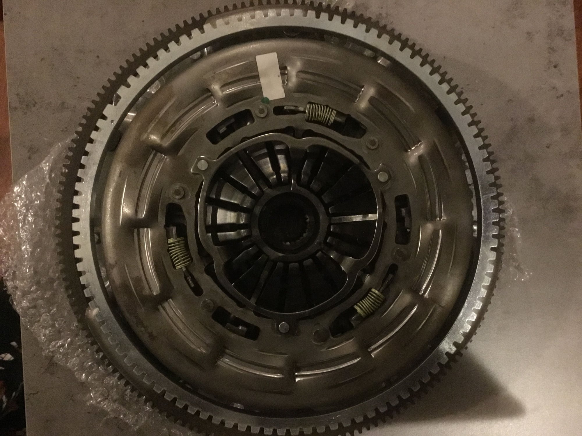
Pardon my ignorance here...it's hard to tell from the pictures. Is the intermediate plate connected by rivet at every other drive strap so one of the clutch discs is trapped between the pressure plate and intermediate plate?
Pardon my ignorance here...it's hard to tell from the pictures. Is the intermediate plate connected by rivet at every other drive strap so one of the clutch discs is trapped between the pressure plate and intermediate plate?
Hi,
If we are talking about the Corvette pressure plate you are correct in that the intermediate clutch plate is trapped (by what means? It is now packed away) and can't be changed separately but at $350 for the assembly you can hardly complain either. Hope this is of some help.
Trapped in a cardboard box haha!! Let it claim its freedom. No glass display case for now?
That exactly answers my question, thanks. I agree with the price it doesn't really matter...I've just never seen that design before. I also wonder how complicated it would be to upgrade the friction material to something like Kevlar if needed. Aftermarket companies will surely spring up and fill that void anyway.
Also, I think most people here wouldn't balk at the idea of a 6 speed transmission. Seven speeds may seem (and indeed be) excessive, but with the rev matching system I think it's an easy choice. I occasionally skip gears on heel-toe downshifting, which must be fairly precise on an early box, and it's more challenging to land the rpm right when skipping gears. If you find you prefer certain gears for certain speeds/types of driving it will likely be much less cumbersome for daily driving with the rev matching capability shifting up and down both. I wonder how the corvette ecu deals with letting the clutch drag a little in neutral. When I upshift my car quickly at high RPM I barely touch the pedal at all as it's coming out of gear, because the minimal drag through neutral will decelerate the input shaft to "line up" the next gear. The engine decelerates a good bit quicker than the input shaft and torque tube on its own. By the time I hit the next gear the clutch is disengaged to prevent a crunch from whatever minor difference exists. When it goes right pushing the clutch down is in one motion (not back up for neutral) if timed perfectly. I do downshifts the same way with a small amount of clutch engagement to speed up the torque tube before engaging gear. I don't see much point in rev matching just the engine and abusing the gearbox. In a perfect world you wouldn't even need syncros...anybody up for a Hewland crash box?? If the system can handle a quick bit of clutch drag, albeit easier said than executed, you could shift at any rpm you wish and keep your original radical plans for your motor. Surely the bearings, friction, and centrifugal force of internal parts wouldn't be an issue until closer to 10,000 rpm.
Then again, if you had an ecu capable of rev matching abilities...a simple hall sensor setup on the torque tube and the handy g sensor from the corvette shifter (or a worthy copy designed) could make a dog box smooth as butter on the street aside from going in to gear from neutral at a stop. Riding motorcycles is always gratifying to me when the power seems seemless from perfect timing and rpm matching. Then again, it's easy for bikes I think because the transmissions have less inertia and spin slow (because the primary reduction). If the ecu was monitoring a fairly high resolution speed sensor from the differential (not sure if the factory part has enough teeth to work) then it should work like the new corvette system. Ecu reads shaft speed difference, shifter anticipates intended gear, and ecu commands throttle to respond accordingly.
Last edited by entropy_engineering; 01-20-2016 at 09:11 AM.
Well this project hasn�t had an update for a long time, over two years which is pretty sad but an indication of the difficulty and my time constraints also. However, it is not abandoned, none of my projects are abandoned and I am looking to increase my tooling and ability to do these jobs all the time. I don�t have the specific tools for this job as it�s extremely technical.
��To recap I am not using the Corvette differential, I am not trying turn my car into a Corvette but use key parts that someone like myself can organise to modify and strengthen the Porsche drivetrain. So many parts of the drivetrain actually become mine in terms of design and manufacture. Those parts are; the flywheel, the upper bell housing the lower bell housing which is being designed to accept the LS starter motor. More on that later. The tail piece of the Tremec transmission and the ring and pinion.
The goals are are to have the most modern hand shifted street transmission that�s possible. Despite numerous lightweight parts, the weight will be close to identical.
Porsche 928 throw out bearing
Corvette C7 Hydraulic Bearing
There is is lots of lightweight parts in the Vette tube, however there is lots of heavy parts too like the couplings.
Now some of those bolts can get a trim, however if I replaced the alloy shaft with a carbon one the weight savings are not dramatic but would be noticeable in terms of rotational weight. So I am reserving my opinion on it�s worth till the car is driven. (Long way off). The carbon shaft often deletes the rubber couplers which is ok for the track but rather crappy for the street. The Corvette has a dual mass flywheel which I won�t have so deleting �the couplers would be a big mistake.
I was highly concerned about the overall length of the drivetrain and would it fit? I did take a gamble there. I have had to scrimp and save every mm. The length I got when I measured a manual car but with a auto crossmember (they sit back about another 15 mm) was from the tip of the input shaft to the centreline of the rear drive axles was 2186 mm.
Then we we put the Corvette�s tube into the 928 tunnel and did some measurements, it�s very tight with such a big tube! The parts need to be CADed but where I need to save a lot of length is where the Tremec box will mate with the Porsche auto differential housing. I must delete the sandwich plate to save 35 mm. Fortunately and I do mean really fortunately there is some space to steal from the Tremec box. It will integrate really well. The other area that will be chopped to save length is the front input shaft. 30 mm to be cut from there.
The pilot bearing ID is actually the same but this will be chopped as the pilot bearing is further into the crankshaft on the Vette. So the saving of a total of 65 mm gives me a total length of 2180 mm. If my measurements are out a bit, there is some wiggle room with the front shaft I believe.
Two billet bellhousings need to be created at the front of the tube. I will also take that opportunity to fit a LS starter. They weigh only 3 kgs and have better ground clearance. You�ll note that the throw out bearings have the same weight, however the Vette doesn�t need the cast iron arm or ball. The starter is lighter than even a lightweight 928 starter and the torque tube weights are 5 kgs in favour of the Vette. However the clutch is much heavier on the Vette. Overall it�s a wash in terms of weight. However the Vette box is much stronger and faster shifting especially with its billet shifter.
What�s the most difficult part, pretty much all of it, I have to design a very compact pinion and it�s a unique design due to the unusual nature of this conversion. It�s an extremely tight fit so I hope I don�t need any more space.
What needs Ed�s to be done? Well I now have a solid plan but I will not rely on anybody else to draw the components, generally I have been let down here by others. Currently the plan is to buy a 3D laser scanner and software to scan it into CAD. The issue here is two fold. I don�t have that training as yet. I have been starting to learn it though. SolidWorks which is my preference is very big bucks at around $7,500 USD. The same sort of price for the scanner and software. I�m treating like a potential business, not the 928 business but learning CAD and 3D scanning.
Solidworks did did years ago offer me a student edition to use because what I was doing was not commercial, this is what�s really needed I think.
Glad to see this is still alive. When I was looking into a one-piece driveshaft for my Cayenne Turbo S with the guys from www.driveshaftshop.com, they offer both a CF and an aluminum version. The CF version actually has less torsional rigidity than the aluminum one, which they said would make the drivetrain smoother. I actually went with the aluminum one, but I wonder if its for this reason that the CF ones eliminate the rubber couplers (because the shaft inherently dampens itself).
Glad to see this is still alive. When I was looking into a one-piece driveshaft for my Cayenne Turbo S with the guys from www.driveshaftshop.com, they offer both a CF and an aluminum version. The CF version actually has less torsional rigidity than the aluminum one, which they said would make the drivetrain smoother. I actually went with the aluminum one, but I wonder if its for this reason that the CF ones eliminate the rubber couplers (because the shaft inherently dampens itself).
�All I can say is the reviews I have read have said don�t eliminate the couplers, our standard drivetrain is damped by the wind up in the thin steel shaft. I would imagine the NVH is going to be worse too. I tend to err on the side of caution on these issues, not that much to gain.
To move all my projects along but particularly this one, I bought a 3D scanner and some pretty impressive software. The scanner can operate hand held of desktop. Accuracy will hopefully be o.k, it�s 0.05 mm or just under 2 thou. There is lots of scanners more accurate but have you seen the price! Anyway the scanner can also be used to scan the entire car and convert it to a CAD file. The software includes a CFD parkage which I have no idea how to use but who knows later down the track. The aero mods I am doing on one car would be interesting to analyse.
So the plan is now to learn how to use this equipment and tools and create the CAD files needed for machining. Also the accuracy I need to ensure things like the spigot shaft lines up perfectly with the back of the crank when I make the new bellhousing. Also we can assemble the drawn parts on the computer to look at clearances and positional relationships. I plan to use the LS starter of previously mentioned, by having everything drawn we should be able to get the starter correctly positioned in relation to the ring gear. The bellhousing (2 pieces) is about $500 USD in material so I don�t want to have two goes at it.
I used to build CAD models from scanned geometry just like what you are planning on doing. It's an artform. If you are hoping to pull machined features off of the scan data it might be difficult to accurately measure the locations to establish feature centers. When I reverse engineered a couple of bellhousings for Quarter Master, that they had lost the original drawings and tooling for, I had the castings probed by a CMM gantry machine to get super accurate centers, sizes, and location for all the machined holes and surfaces. I would then use the scan data to build the organic casting shape and then merge the scan data together with the CMM data to place all the machined features onto the casting. The casting will have all kinds of manufacturing variances, especially if it was located poorly in the machining fixture of if the original pattern was worn or at the end of life, so be sure to use your best engineering judgement to center the two datasets together. If it looks close to being symmetrical, it probably is. The guy I used to work for never understood that and actually wanted me to model in the shrinkage. It was comical. Good luck with it, it's like putting together a digital puzzle trying to figure out how each feature was made by the original engineer/designer...
Well im glad we�re on the same page, this is exactly what I�m expecting even though I have zero experience with CAD but have been doing various tutorials. I have Siemens Solid Edge ST10 which is the current version. It doesn�t have the cam tools but I think I have enough to learn..... How do you think I�m going to go at 0.05 mm tolerance? My plan is to go with this accuracy to develop the CAD model and then on parts like the housing for the 7 speed transmission get my model checked on a CMM or maybe with a touch probe on a mill. On other less critical parts I�m going with that standard.
Originally Posted by UNEEKONE
I used to build CAD models from scanned geometry just like what you are planning on doing. It's an artform. If you are hoping to pull machined features off of the scan data it might be difficult to accurately measure the locations to establish feature centers. When I reverse engineered a couple of bellhousings for Quarter Master, that they had lost the original drawings and tooling for, I had the castings probed by a CMM gantry machine to get super accurate centers, sizes, and location for all the machined holes and surfaces. I would then use the scan data to build the organic casting shape and then merge the scan data together with the CMM data to place all the machined features onto the casting. The casting will have all kinds of manufacturing variances, especially if it was located poorly in the machining fixture of if the original pattern was worn or at the end of life, so be sure to use your best engineering judgement to center the two datasets together. If it looks close to being symmetrical, it probably is. The guy I used to work for never understood that and actually wanted me to model in the shrinkage. It was comical. Good luck with it, it's like putting together a digital puzzle trying to figure out how each feature was made by the original engineer/designer...
O.K, we have some progress, albeit a little minor but important in the scheme of things, I am in a position where I had to learn CAD and 3D scanning. My CAD system is Solid Edge, it's quite good but my problem is that I don't know CAD at all and I have had to teach myself from YouTube videos, as you can imagine this is very slow and fraught with mistakes and not knowing the quickest way to do jobs. However trying to explain complex jobs to tradesman is also a problem and the cost might be astronomical.
So with the mini stroker engine, this engine will have a solid 500 HP and because I don't want to break a gearbox or clutch, I have decided to build the same clutch setup for the factory GT transmission as I will build for the 7 speed version. This means custom flywheel, upper bellhousing and lower bellhousing. The lower bellhousing will hold the LS starter. The LS starters are extremely good and small, they only weigh 3 kgs and that is less than the lightweight starters that don't turn over as quick. So that is a no brainer really. So those three parts are common to both systems. The other improvement is that I'm using the aftermarket billet shifter made for the Corvette. It's extremely precise, like a rifle bolt in fact. A one off piece that is required will be the rear housing for the torque tube on the Porsche. This is not needed when I do the 7 speed as that torque tube is complete.
With this project I was really in the dark, I had no idea whether it could be made to work. So far it looks like it's feasible. The big issue is length, the Corvette is a very long car compared to the 928 when you look at the wheelbase. So it's very lucky it it looks like fitting. I've had to steal every mm I could find. When I started I had no idea what the flywheel would look like, it was somewhat surprising, the new flywheel will still use the factory ring gear and timing ring. This is one of the issues, in this photo you can see the physical size of the Corvette clutch, it's quite massive.
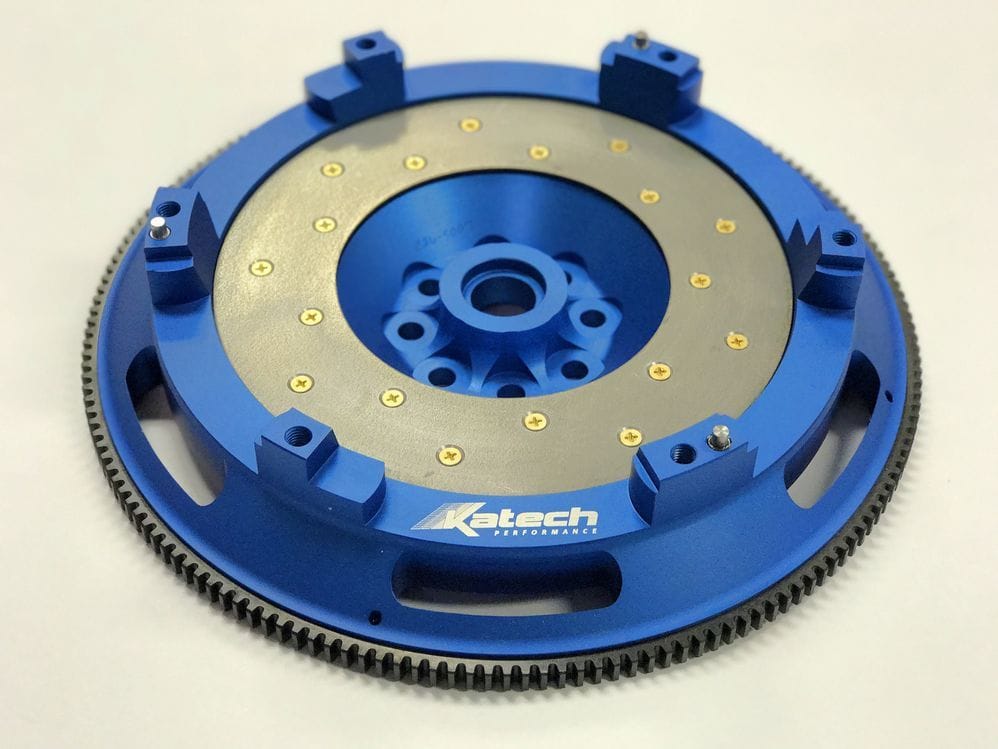
So the current C7 Corvette uses a stepped flywheel, so this is the reason the factory/aftermarket flywheels look like the one below, those posts have to hold a lot of torque, so will mine. I can still tweak my design in fact it looks like the constraint for the ring gear needs adjusting which won't hopefully be too hard.
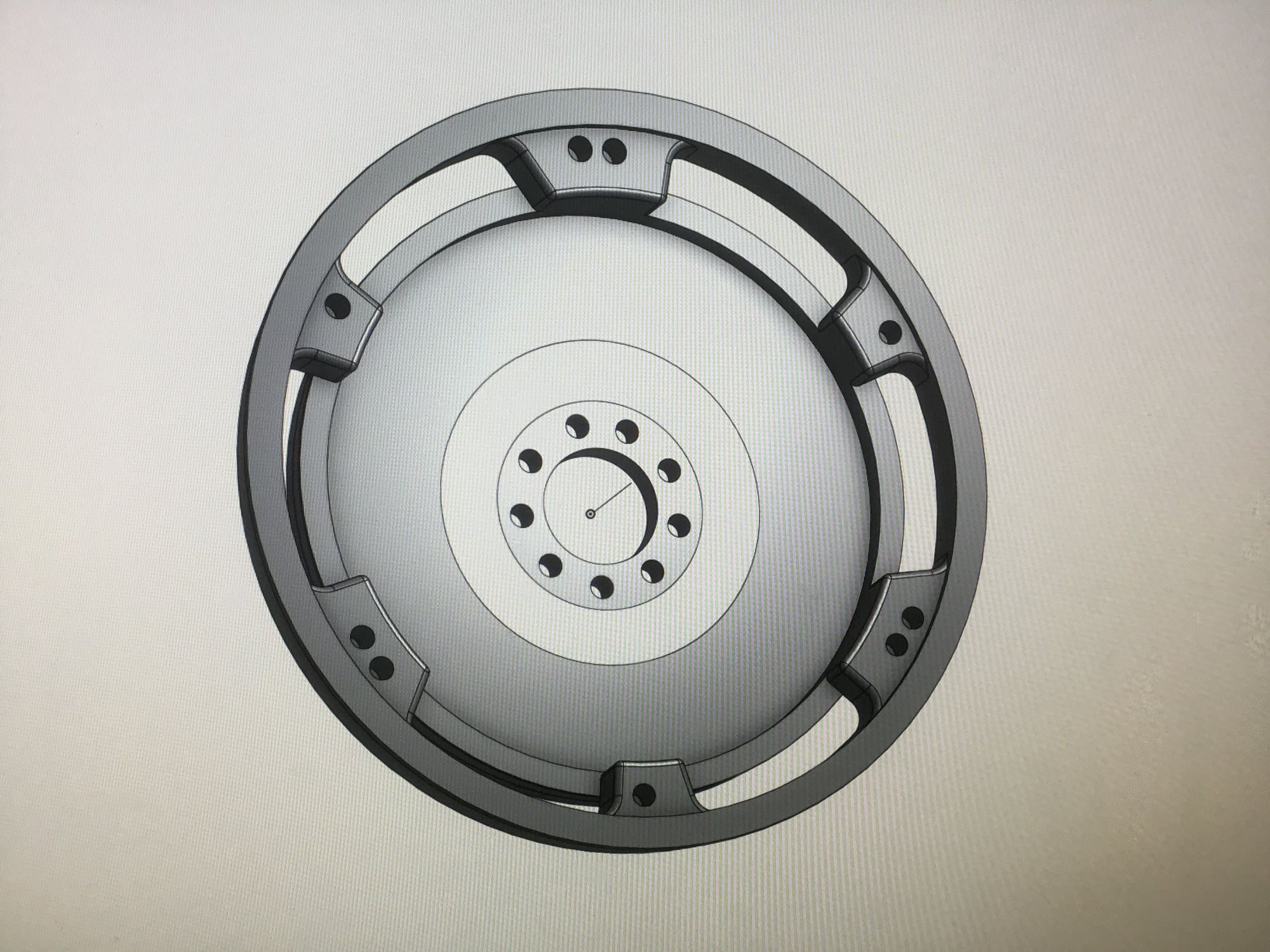
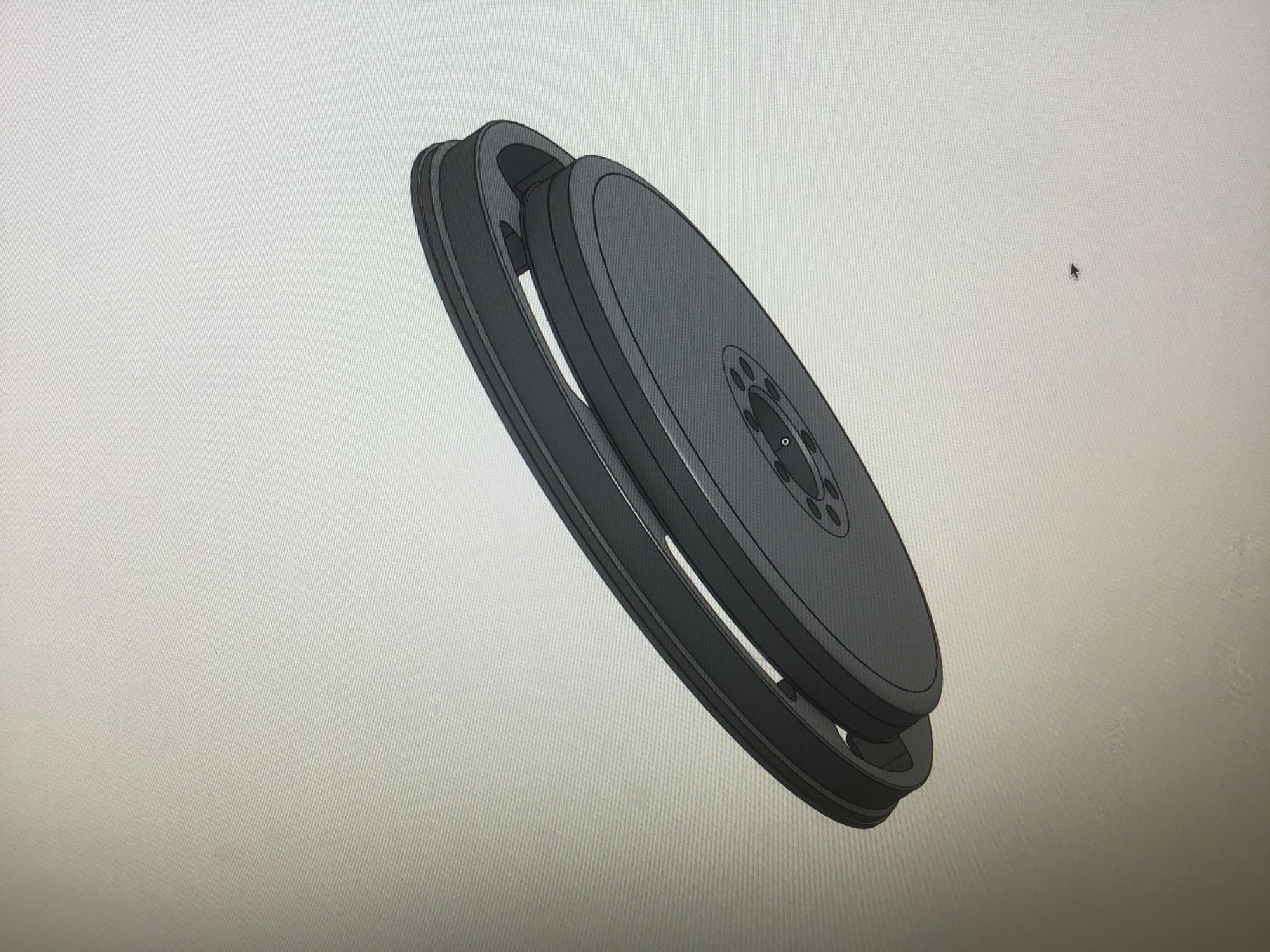
Then we have mine, I haven't drawn the ring gear or timing ring, it's not worth the time when you are an amateur like me. However it will get drawn when we measure the placement of the starter motor so that I can accurately match up the pinion to the ring gear. My flywheel will incorporate the Katech flywheel replaceable friction plate. I will also be able to change that insert so that I could use my Tilton carbon clutch with it different bolt pattern. I may but don't whether there may be an issue with the depth of the throw out bearing with the Tilton but I could adjust that a bit with a thicker insert plate.
Ring gear area to be widened
I will have to cut the rear of the crankshaft off where the pilot bearing is housed. It will then need to be rebored to hold the bearing. When I get the stroker crank made this change will be incorporated from the start. It appears I have just enough room to have a 4" thick (long) bellhousing. The Corvette torque tube bellhousing is quite big having 8 large bolts. Roughly it is a 200 mm diameter. I will do some more calculations and drawings in the near future.
Be careful with that Hydraulic TOB from the C7. It gets the fluid dirty in about 1000 miles. If you do better than GM did and actually make it a clear path for someone to bleed it from the bottom, then great. But something in the system picks up dirt very quickly, IN the fluid.
Be careful with that Hydraulic TOB from the C7. It gets the fluid dirty in about 1000 miles. If you do better than GM did and actually make it a clear path for someone to bleed it from the bottom, then great. But something in the system picks up dirt very quickly, IN the fluid.
That's a really good point about the hydraulic TOB, I didn't know of the problem but I did see a bleeding kit made for these. I wondered why initially, well I am going to try to use the Porsche master cylinder, so that's half the system... Will there be a problem? No idea on that. On my Porsche transmissioned car, I could in theory rotate the bearing so that the cylinder still faces upwards but on the side for easier access or maybe after investigation have a hose or pipe with a tap?
I did a measure today with a tape so somewhat inprecise, it appears that the 7 speed is exactly the same length as the automatic version of the 928 drivetrain. So it will be tight, that measurement depends on myself designing a the rear housing of the TR 6070 to fit the Porsche automatic differential and as such not adding to the length with a sandwich plate type adaption. This does appear possible at this point, it's a risky project as nobody has guaranteed this will work, just like the clutch arrangement nobody knew whether it would fit, it now appears to be not a problem. It is probably only a 1/3 of the job though.

 01-19-2016, 11:06 PM