
S4 intake manifold facts and ideas
 05-11-2013, 09:08 PM
#1
Nordschleife Master
Thread Starter
Is anyone who has the flow bench data on the S4 intake manifold willing to share those data?
I am looking for the steady flow numbers for each of the runners, with the plenum covers on (sucking thru the vertical secondary pipes) and with the plenum covers off (suck free air). That's 16 numbers which is a lot to ask, but if someone has them I'd love to see them.
My purpose is that I am trying to understand the stock S4 manifold a little bit better. Perhaps there are some things that one could do to get the manifold to work a bit better at high rpms. Any ideas on that topic would also be greatly appreciated.
 05-11-2013, 10:25 PM
#2
Nordschleife Master
Thread Starter
I did a very quick and dirty (literally) measurement of the plenum volumes. I got 1.8L for the passenger side and 1.9L for the drive side with the flappy closed. Tolerances are large, so I would say they are probably both in the 1.7-2.0L range.
The plenum volume is one of the more important inputs to the Helmholtz resonator computations. Hence the motivation.
The plenum volume is one of the more important inputs to the Helmholtz resonator computations. Hence the motivation.
05-11-2013, 10:36 PM
#3
Nordschleife Master
Thread Starter
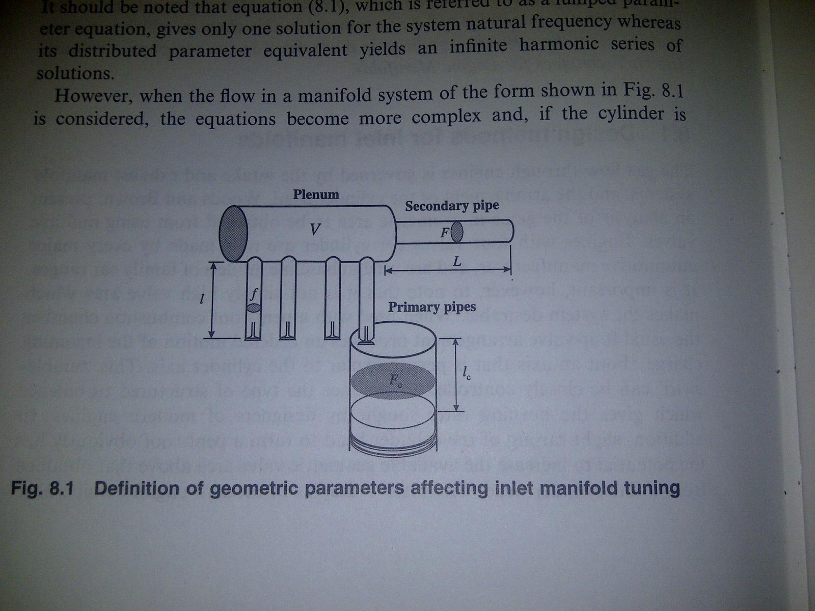
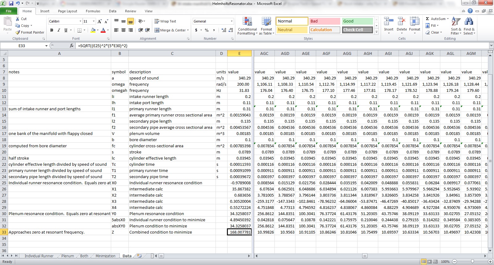
I tried to punch in the numbers from the "Theory of Engine Manifold Design" p. 440-441 to Excel. It's a set of wave conditions for a two chamber, two pipe Helmholtz resonator system. Before going any further, let's make it clear that I am not confusing my ability to punch in the formulas to a spreadsheet with actual understanding of them.
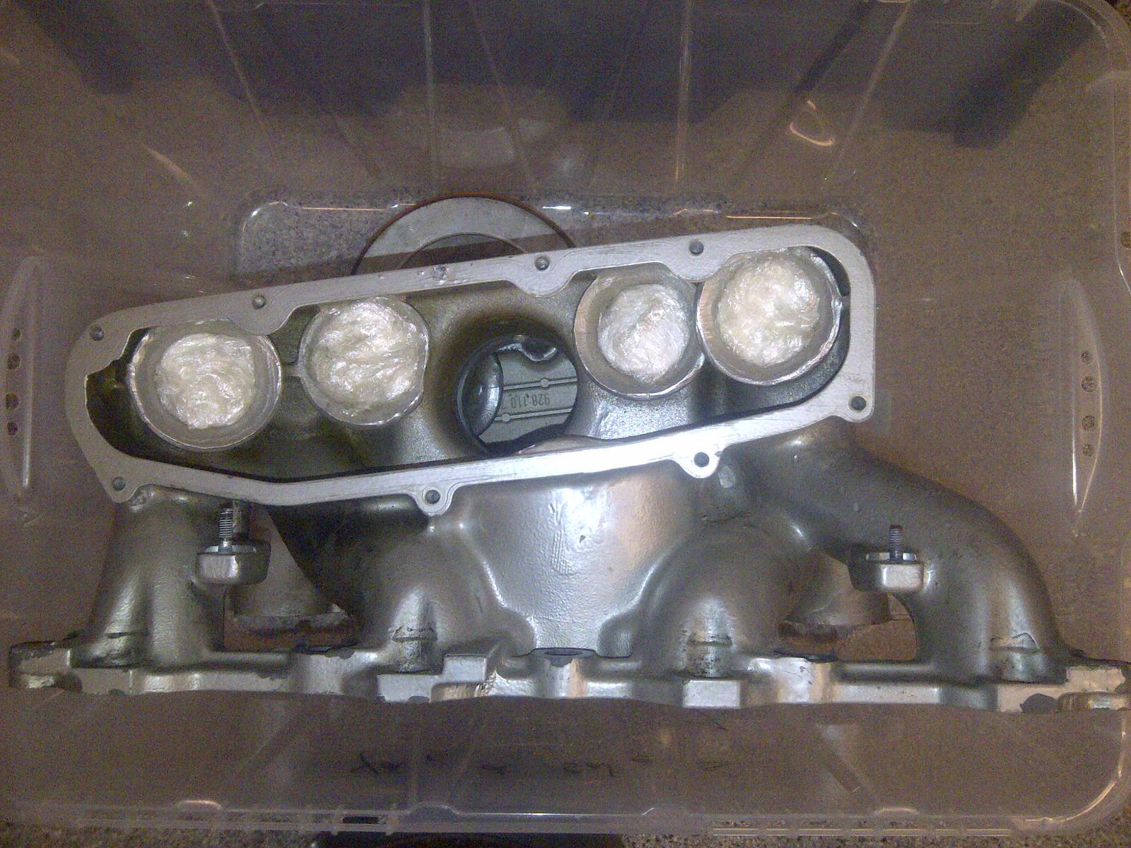
The spreadsheet has my assumed values. Please comment and correct if some of those are wildly off. I am modeling the four shorter intake runners in that screen shot, which average about 20 cm. The longer runners are about 30 cm.
The spreadsheet has my assumed values. Please comment and correct if some of those are wildly off. I am modeling the four shorter intake runners in that screen shot, which average about 20 cm. The longer runners are about 30 cm.
05-11-2013, 10:51 PM
#4
Inventor
Rennlist Member
Rennlist Member
 05-11-2013, 10:58 PM
#5
Nordschleife Master
Thread Starter
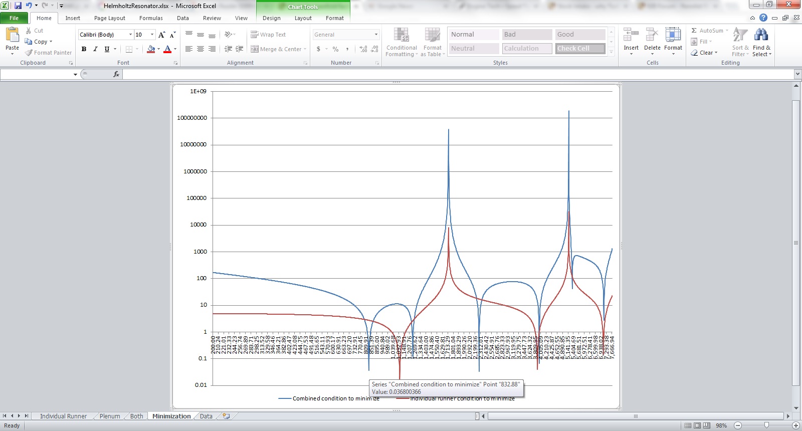
How the spreadsheet works (or at least should work) is that there are two conditions that should both be satisfied. There's what I call an "individual runner condition" which mostly depends on the cylinder cavity and runner resonance. There's also a "plenum condition" which also depends on the plenum volume and the ram pipe (from throttle body to plenum) length and diameter.
The below graphs have a blue line which is measure how well both conditions are satisfied. When both conditions are satisfied increasingly closely, the y axis gets very close to zero. That means that the x axis value at which this happens is a resonant frequency for the system. The resonant frequency is the units of rad/s.
Modeling 20 cm runners:
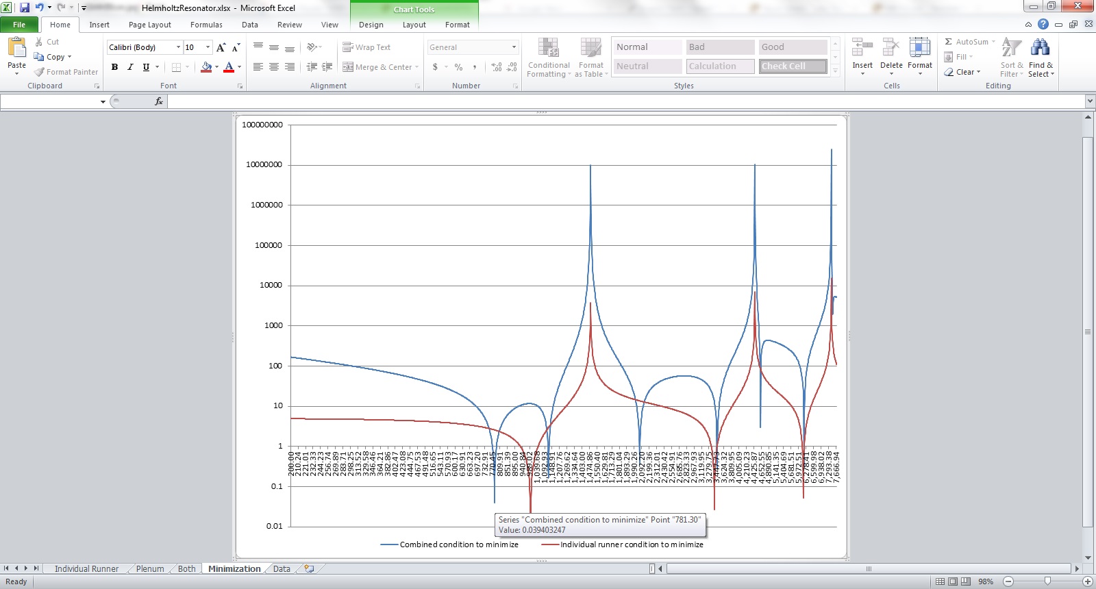
Modeling 25 cm runners:
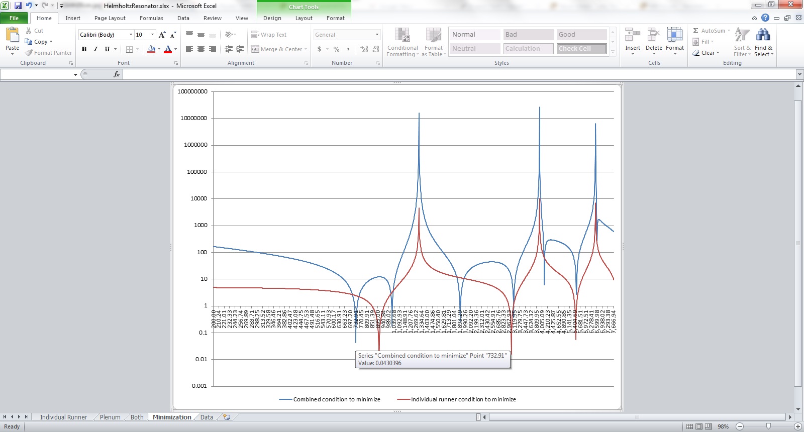
Modeling 30 cm runners:
The points highlighted with the cursor are the points where both the cylinder and the plenum work in tandem. Given the current assumed inputs, the one point where the two conditions are very closely satisfied is 780 rad/s. I am guessing that if the assumed inputs are accurate, this corresponds to the flappy closed torque peak at 3100 rpm.
Does this make sense? The 3100 rpm point corresponds to 51.7 Hz or 324.6 rad/s. The intake manifold returns a pulse in 41% of a crankshaft revolution, or 151 degrees. The S4 intake cam has 205 degree duration. It's plausible that the pulse generation takes some time and then its optimal for the cycle to complete well before the intake valve closes. So this might be correct.
Very big caveat emptor... Just thought I'd post this here so people could expose the errors.
The below graphs have a blue line which is measure how well both conditions are satisfied. When both conditions are satisfied increasingly closely, the y axis gets very close to zero. That means that the x axis value at which this happens is a resonant frequency for the system. The resonant frequency is the units of rad/s.
Modeling 20 cm runners:
Modeling 25 cm runners:
Modeling 30 cm runners:
The points highlighted with the cursor are the points where both the cylinder and the plenum work in tandem. Given the current assumed inputs, the one point where the two conditions are very closely satisfied is 780 rad/s. I am guessing that if the assumed inputs are accurate, this corresponds to the flappy closed torque peak at 3100 rpm.
Does this make sense? The 3100 rpm point corresponds to 51.7 Hz or 324.6 rad/s. The intake manifold returns a pulse in 41% of a crankshaft revolution, or 151 degrees. The S4 intake cam has 205 degree duration. It's plausible that the pulse generation takes some time and then its optimal for the cycle to complete well before the intake valve closes. So this might be correct.
Very big caveat emptor... Just thought I'd post this here so people could expose the errors.
05-11-2013, 11:00 PM
#6
Nordschleife Master
Thread Starter
 05-11-2013, 11:17 PM
#7
Nordschleife Master
Thread Starter
An obvious question is why bother doing this. Here's what I am thinking:
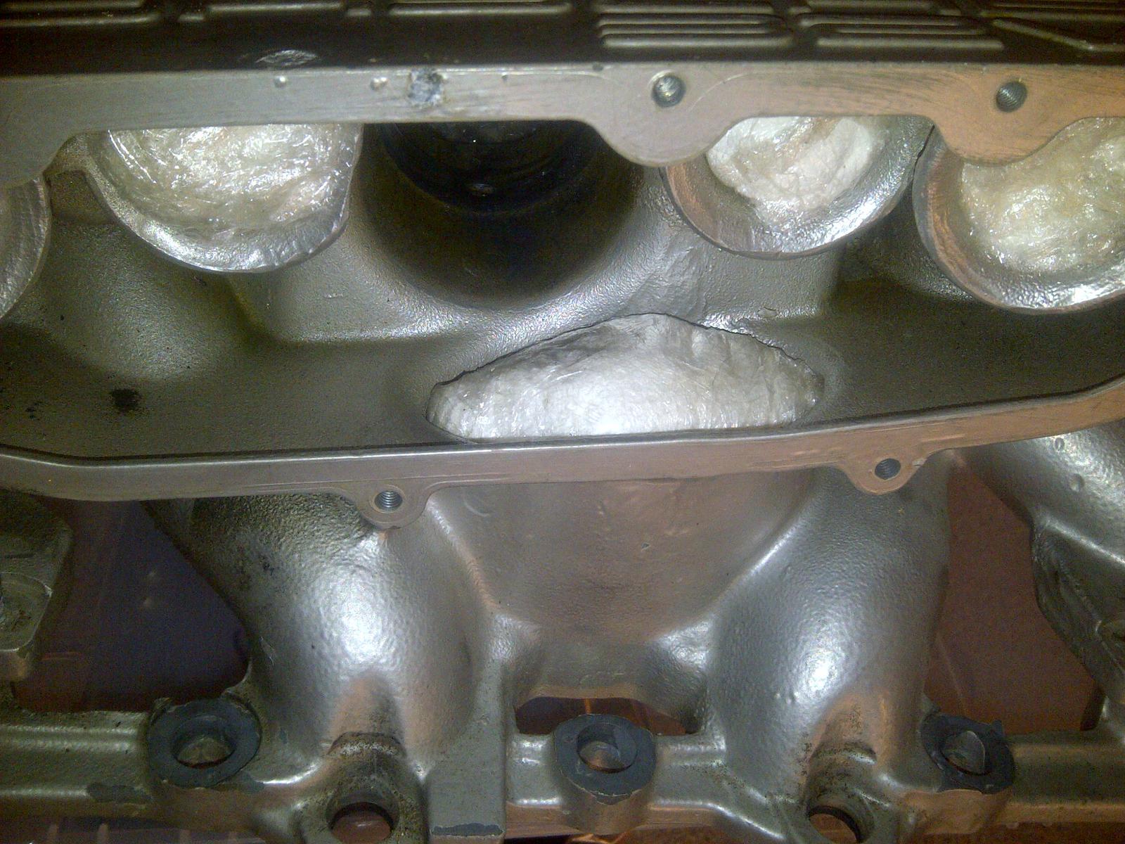
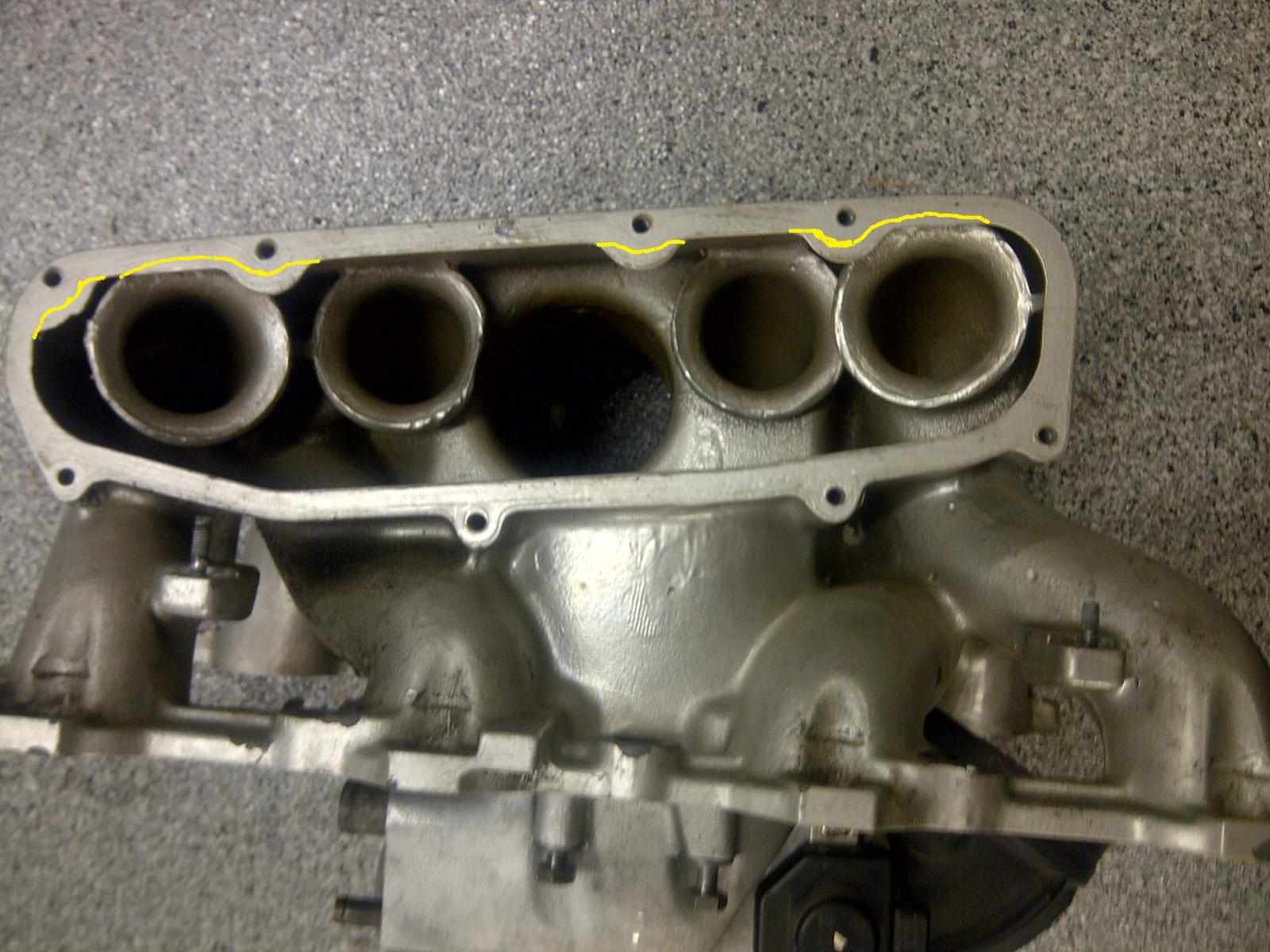
I am going to port one of the intake manifolds a little bit more aggressively. The plan is as follows. Get a spacer for the driver side plenum. Cut off the existing sealing flanges from the main manifold casting. Permanently attach the spacer to the plenum. Shape the spacer such that the inside edge doesn't obstruct flow while the outside edge still provides the sealing surface to the stock plenum cover gasket. The predicted (or hoped for) benefit is that this will solve the flow issues to the problem cylinder number five.
However, in the process the plenum volume expands. Since it's a Helmholtz resonator, this is not necessarily without consequences. I want to know whether I need to fill some of the plenum cavity with aluminum block filler to reduce the plenum volume back to the stock volume (or go part way there, or even reduce it to a smaller volume than stock). That's why I am fumbling with these resonance computations.
Here's the porting plan for the driver side, rough sketch of where to take out some flow restrictions:
So what's the answer, provided that my spreadsheet is correct? Turns out that adding the spacer doesn't move the 3100 rpm flappy closed torque peak much at all. For example, a 20% increase in plenum volume from 1.85L to about 2.2 only reduces the resonance point by about 2.1% or from 3100rpm to about 3036rpm. (Precision in these computations should not be confused with accuracy...)
My conclusion from this is that it's probably not worth it to start playing with block filler.
Trending Topics
05-11-2013, 11:42 PM
#8
Inventor
Rennlist Member
Rennlist Member
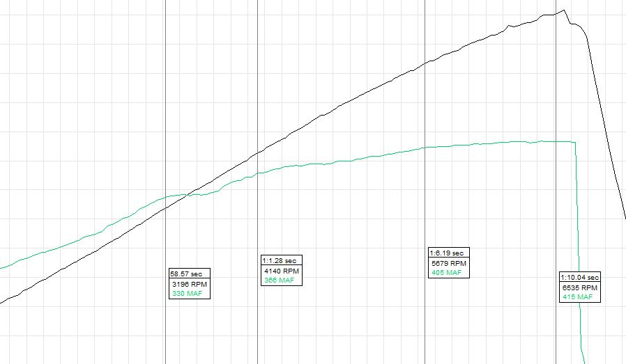
This is a typical log for my 1-mile run in 3rd, '88 5-speed, 46K, stock w/X-pipe.
First three measurements are roughly the peaks from the latest dyno.
The third peak might actually be at a higher rpm, but after 5700, it just doesn't breathe anymore.
30' 55F 30.45" 40Fdew = 106.4 relHP -723 feet
First three measurements are roughly the peaks from the latest dyno.
The third peak might actually be at a higher rpm, but after 5700, it just doesn't breathe anymore.
30' 55F 30.45" 40Fdew = 106.4 relHP -723 feet
05-12-2013, 12:06 AM
#9
Nordschleife Master
Thread Starter
What would be very helpful if someone would post or repost dyno graphs with otherwise mostly stock engine but that has bigger cams and loud exhaust. How does the torque curve look up there above 5500 rpm without those baby-girl-in-pink S4 cams?
05-12-2013, 12:13 AM
#10
Nordschleife Master
Thread Starter
This one I can't figure out at all. Basically the computer says "does not compute" and brain risks an aneurysm when trying to understand how would it conceivably be possible that these intake spacers would be worth 10 hp at the top end. Especially if it's an otherwise stock car with the stock ECUs that close the flappy at high rpms. The flappy-closed mode should bring further down any resonance points and help the bottom end and hurt the top. So where did these ten ponies (or maybe unicorns) come from?

05-12-2013, 02:23 AM
#12
Nordschleife Master
Colin - did Terry's car ever get to a dyno with the large exhaust on it too?
I recall seeing the dyno sheets with stock exhaust and your cams.. but can't recall seeing a follow-up, which would be the kind of graph Tuomo's asking for in post 9.
I recall seeing the dyno sheets with stock exhaust and your cams.. but can't recall seeing a follow-up, which would be the kind of graph Tuomo's asking for in post 9.
05-12-2013, 03:04 AM
#13
Nordschleife Master
Hilton,
We did dyno it and it put down 352rwhp.
But I was unable to adjust the fuel mixture, it was either 12.2 or 13.1 with no variance.
I have determined this to be an injector problem. The new injectors are on the way, and we will be reworking everything soon!
We did dyno it and it put down 352rwhp.
But I was unable to adjust the fuel mixture, it was either 12.2 or 13.1 with no variance.
I have determined this to be an injector problem. The new injectors are on the way, and we will be reworking everything soon!
05-12-2013, 06:11 AM
#14
Rennlist Member
Tuomo, Greg Brown has lots of experience of modifying the stock intake to go with his strokers. He may have some of the measurements you are asking for.
Threshie did some measurements of the stock manifold, they were published in the now defunct "928 Forum" magazine. Have you seen that article ?
Threshie did some measurements of the stock manifold, they were published in the now defunct "928 Forum" magazine. Have you seen that article ?
05-12-2013, 08:48 AM
#15
Nordschleife Master
Thread Starter
Tuomo, Greg Brown has lots of experience of modifying the stock intake to go with his strokers. He may have some of the measurements you are asking for. Threshie did some measurements of the stock manifold, they were published in the now defunct "928 Forum" magazine. Have you seen that article ?
Here's the Treshie article if someone is interested:
https://picasaweb.google.com/1059510...eat=directlink
The most relevant page:
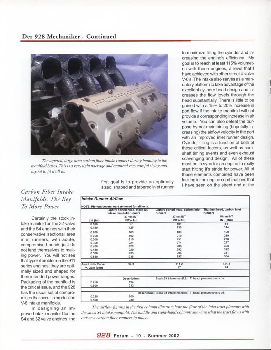
in. cfm cfm %
Lift Stock manifold runners Straight runners Gain Pressure drop ratio
0.1 97 101 4% 0.922
0.15 126 136 8% 0.858
0.2 166 183 10% 0.822
0.25 192 219 14% 0.768
0.3 210 251 20% 0.699
0.35 221 274 24% 0.650
0.4 226 286 27% 0.624
0.45 229 292 28% 0.615
0.5 233 296 27% 0.619
0.55 235 297 26% 0.626
I am still trying to wrap my head around it how is it possible that the stock manifold is so large of an intake restriction even at low valve lifts. I was surprised by the above numbers. And they are not runner specific in any case.
So what's the problem with the stock intake? It's not the runner diameter alone, because huge power is made in other 4V engines with intake runner diameter 120% of the intake valve diameter. That's about 45mm runners for our 37mm intake valves. Plus the ancient wisdom is that extrude hone to increase the diameter doesn't help. It's not pulse tuning, because we're talking about steady state flow. It's not just the plenum because these numbers are with the cover off. If it's the sharp turns in the runners, then some of the runners which don't have those sharp turns should flow gangbusters? And that's one of my motivations for asking for the runner specific flow data.
Maybe it's the case that the stock manifold can't be made to flow what the 37mm valve head can be made to flow, but hopes springs eternal...