
Newest Project - Lower Intake Manifold for Fabricated S4 Intakes
 04-25-2013, 12:27 PM
#46
Developer
This is the set of intake runner that we make that Hans referred to.
The customer can add the plenum and throttle bodies he wants, or ITB's.
http://www.928motorsports.com/parts/intake_runners.php
Made in glass-filled nylon, it is half the weight of aluminum, and less heat conductive to maintain a cooler air charge into the cylinder. It has proven itself to be very tough for us, at 104 deg F track days and with pressures up to 20 psi in the plenum.
 04-25-2013, 06:36 PM
#47
Rennlist Member
Thread Starter
Dan,
I have done some basic modeling, and an "AMG style" system will not fit very well. It could be done, but the injectors would have to be relocated and the intake runners vertical (like they are in the AMG setup).
I can think of plenty of other interesting things do do with these though.
Hans
I have done some basic modeling, and an "AMG style" system will not fit very well. It could be done, but the injectors would have to be relocated and the intake runners vertical (like they are in the AMG setup).
I can think of plenty of other interesting things do do with these though.
Hans
04-25-2013, 06:37 PM
#48
Official Bay Area Patriot
Fuse 24 Assassin
Rennlist Member
Fuse 24 Assassin
Rennlist Member
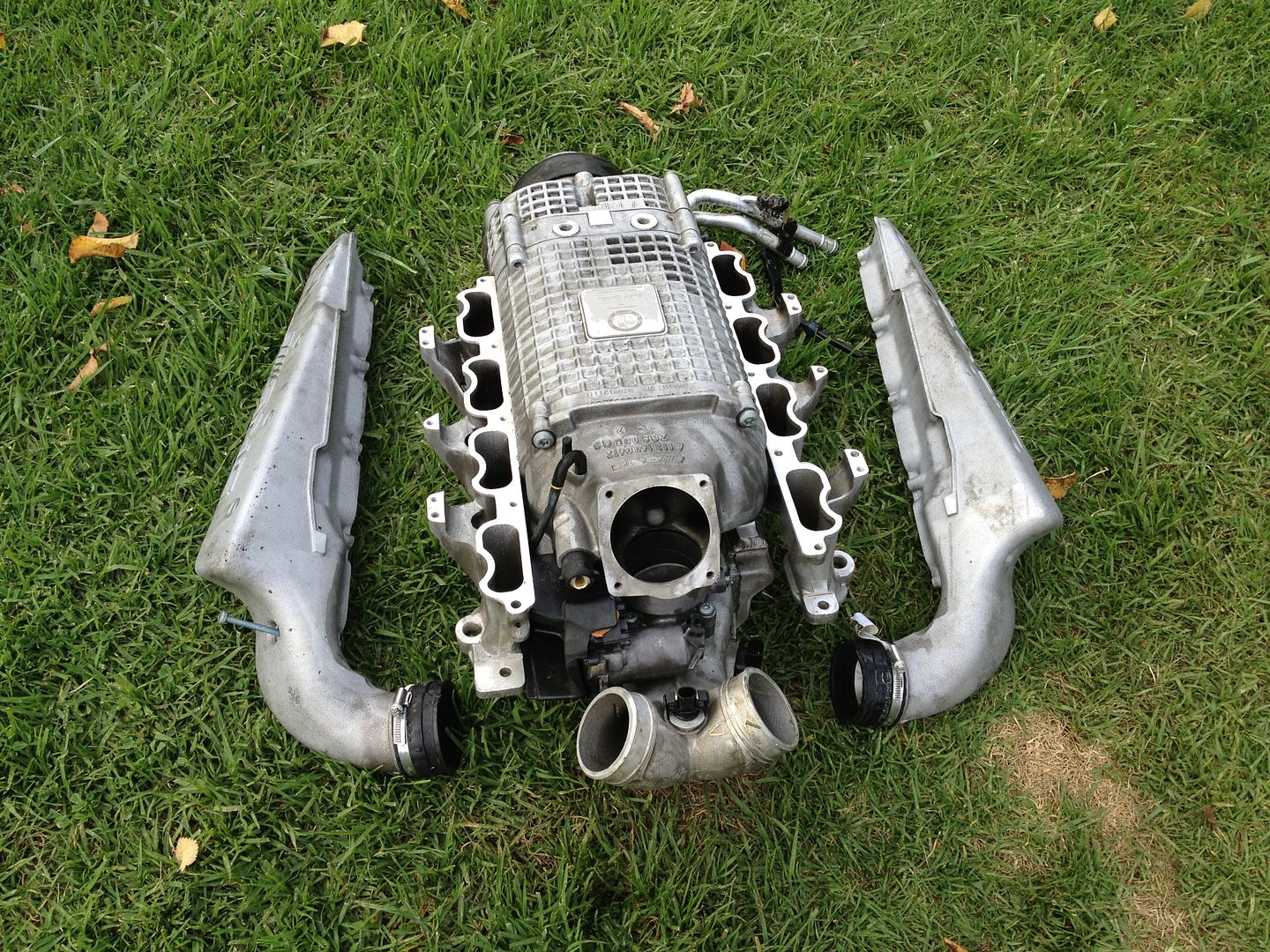
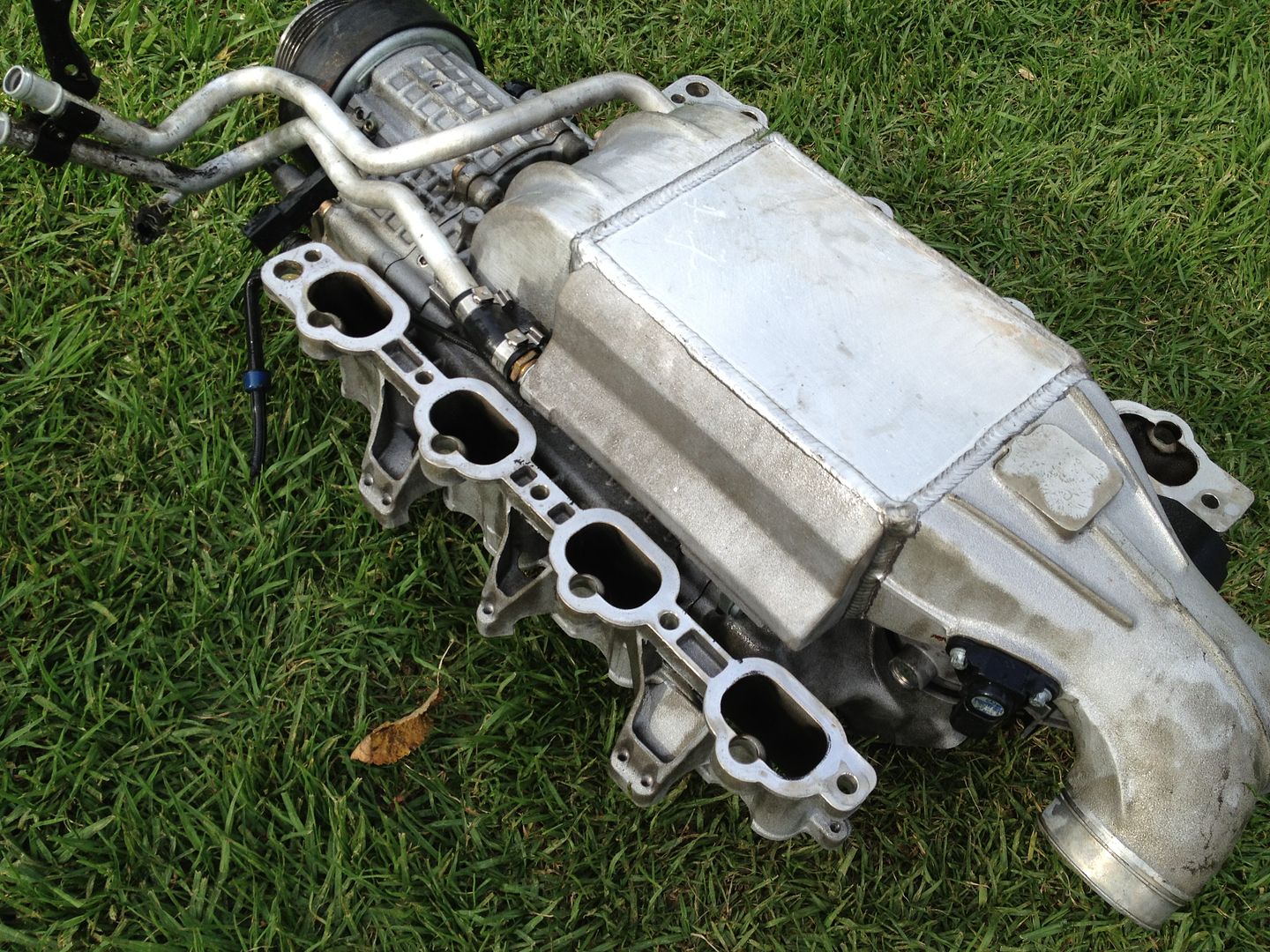
The setup of the M113 V8's supercharger is gorgeous on the AMG. That Manifold would definitely look good on a 928. I'm a little stumped on where to put the MAF and throttle body though. This setup may need to utilize a MAP type EFI and dual throttle bodies, which may not be too difficult to setup.
Now you're talking. And if you could fabricate some rectangular boxes which connect to a Y-pipe in the rear that connect to an intercooler in the engine-V which then connects upwards into a twin-screw supercharger, you will have almost perfectly replicated an AMG setup. I wonder if an E55 intercooler would fit in the V of the 928 engine; I'm pretty sure it would...


Dan
'91 928GT S/C 475hp/460lb.ft
Dan
'91 928GT S/C
475hp/460lb.ft 04-26-2013, 02:47 AM
#52
Archive Gatekeeper
Rennlist Member
Rennlist Member
Behold the power of the internet:
RL Search for Chris Lockhart led to this:
https://rennlist.com/forums/928-foru...hood-pics.html
With broken links, but the URL was there, which leads to:
http://members.rennlist.com/pirtle/bigunn_hood.html
RL Search for Chris Lockhart led to this:
https://rennlist.com/forums/928-foru...hood-pics.html
With broken links, but the URL was there, which leads to:
http://members.rennlist.com/pirtle/bigunn_hood.html
04-26-2013, 11:44 AM
#54
Rennlist Member
Thread Starter
Exactly right. I have an idea that I have been working on which will require a controlled height.
I had been thinking about doing runners for a while, and when Carl released his, I took a look at them and thought they were a very nice design, and that I probably couldn't have done any better. (I still think that if you needed an easy to work with part, and your design wasn't height or width constrained, that Carl's runners offer a quicker assembly time, with the added benefit if thermal isolation.)
However, when I started taking a look at my original plans again this winter, I realized that I did need a considerably shorter setup, and something with more separation between the right and left flanges, so I would not be able to use the excellent parts that Carl developed.
That is when I went back to my original drawings, and started the process which yielded the design I proposed recently. I can tell you that this is not a simple part to create, and I absolutely commend and applaud both Carl's runner design and Greg's manifold. I can personally testify to the amount of shear time that goes into a design like this.
I do need a couple sets of these flanges for my own project, and will make them. If anyone else is interested, please let me know, as it will help guide the way in which I have these produced.
Thanks,
Hans
04-26-2013, 12:05 PM
#55
Developer
Kudos to you, Hans, for taking on such an involved project.
We found injector placement in the runner to be quite a challenge too - to both optimize spray pattern but also to allow the plenum we wanted to fit over the top of the injectors, and connect them all to a common fuel rail. Too low - bad, too high - bad. Too far to the sides - bad. You know what I mean.
I like your design, best of luck with it. Let me know if I can be of any help.
04-26-2013, 01:08 PM
#56

Exactly right. I have an idea that I have been working on which will require a controlled height.
I had been thinking about doing runners for a while, and when Carl released his, I took a look at them and thought they were a very nice design, and that I probably couldn't have done any better. (I still think that if you needed an easy to work with part, and your design wasn't height or width constrained, that Carl's runners offer a quicker assembly time, with the added benefit if thermal isolation.)
However, when I started taking a look at my original plans again this winter, I realized that I did need a considerably shorter setup, and something with more separation between the right and left flanges, so I would not be able to use the excellent parts that Carl developed.
That is when I went back to my original drawings, and started the process which yielded the design I proposed recently. I can tell you that this is not a simple part to create, and I absolutely commend and applaud both Carl's runner design and Greg's manifold. I can personally testify to the amount of shear time that goes into a design like this.
I do need a couple sets of these flanges for my own project, and will make them. If anyone else is interested, please let me know, as it will help guide the way in which I have these produced.
Thanks,
Hans
I had been thinking about doing runners for a while, and when Carl released his, I took a look at them and thought they were a very nice design, and that I probably couldn't have done any better. (I still think that if you needed an easy to work with part, and your design wasn't height or width constrained, that Carl's runners offer a quicker assembly time, with the added benefit if thermal isolation.)
However, when I started taking a look at my original plans again this winter, I realized that I did need a considerably shorter setup, and something with more separation between the right and left flanges, so I would not be able to use the excellent parts that Carl developed.
That is when I went back to my original drawings, and started the process which yielded the design I proposed recently. I can tell you that this is not a simple part to create, and I absolutely commend and applaud both Carl's runner design and Greg's manifold. I can personally testify to the amount of shear time that goes into a design like this.
I do need a couple sets of these flanges for my own project, and will make them. If anyone else is interested, please let me know, as it will help guide the way in which I have these produced.
Thanks,
Hans
04-26-2013, 02:38 PM
#58
Rennlist Member
Thread Starter
Carl
Thanks for the kind words. It really is exactly as you say - there is no room for those injectors. Trying to cast the manifold proved an additional challenge as most foundries will do a minimum wall thickness of 3.5mm, and almost any design kept interfering with the injector when maintaining walls with proper thickness and draft, which is why I had to switch over and use tubing for the upper portion.
It really was a frustrating exercise of moving the clearance issue from one location to another.
When researching injectors (ignorantly in the beginning I thought that perhaps the new short EV14 or Deka injectors would help solve the clearance issue) I found that the Siemens Deka used in GM applications, part number FI114357 is both quite affordable, and also has a split spray pattern with an angle that almost exactly points the spray cone at the back of each intake valve when installed in a stock position (height needs to be altered slightly). It does use a USCAR type connector, but converter plugs are available, and the price including the adapter is affordable. Its is the only affordable high-volume (44lb) linear injector i have been able to find with a split spray. The new EV14 have several split spray injectors, but they are over $175/each as opposed to this ~$50 injector. I still need to actually buy one, and install it in a clear mockup manifold to verify the spray pattern installed, but it models correctly in my software. I will be sure to share data when I get it, but if you happen to get a chance to take a look, it may be a good fit for your design as well.
Here is a link to that injector datasheet.
Mongo
With a flange like this, all you would need to buy is a 45degree bend, cut it at a 22.5degrees, then weld it to both a flat plate and the flange, and you would have an optimized version of the original Keel concept - albeit with a slightly raised mounting height - but that is just added room for the intercooler and to clear the water bridge.
The idea here was to make a building block that could be used for something like a supercharger installation, but also a cross-runner system like the old 928Developments intake.
Its not a bolt-on part (we already have a great example of that available from Carl) but something more versatile for those who have access to fabrication equipment and an idea kicking around that they want to try.
Hans
Last edited by hans14914; 04-26-2013 at 02:56 PM.
04-26-2013, 02:53 PM
#59
Addict
Rennlist Member
Rennlist Member
Join Date: Feb 2004
Location: Monterey Peninsula, CA
Posts: 2,374
Likes: 0
Received 16 Likes
on
12 Posts
Hans,
Not trying to rain on your parade here, but I did not have issues with the injectors. they are all available as solidworks models from Bosch, and you can fit them in your assembley file and have the software clearance them for you... I thought the more important items were height, and angle, based on spray pattern and expected flow of air..
The injectors were easy, all the other bits were difficult on my setup...
Hmmmm, food for thought.. everyone's different..
cheers,
04-26-2013, 03:02 PM
#60