
DIY PSD-unit swap out procedure.
 03-04-2012, 05:09 PM
#1
Rennlist Member
Thread Starter
Lengthy write up, with 42 photo's in all. If you need a high res picture of any of these, then PM me.
I. Acknowledgements:
1. Hacker-Pschorr: for providing upfront permission to me (many months ago, writing this procedure out is way overdue by me!) of informing about the next line (to which I have no affiliation, just being a very happy customer!).
2. Harald Stein, who is THE expert in PSD-unit repairs and the person to go to if you live in Europe. More information on Harald's web-site:
http://www.stein-aviation.de/html/psd_engl.html
3. Louis Ott and John Veninger, for their documented "PSD FLUID FLUSHING PROCEDURE" write up (as for example stored here: http://www.928intl.com/repair/psd1.pdf )
4. Dwayne: for the always incredible amount of details in his write up's for this 928 community, and thereby being my inspiration for doing this procedure write up.
II. What is the problem:
1. When the PSD-unit (as standard on all 1990 and onwards 928) is not regularly serviced every 2 years by flushing the PSD hydraulic (brake)fluid, sooner or later the pump will seize up. Once the pump is fully seized up, then sooner or later the pump electric coils will overheat and then either melt through or short circuit - resulting into a fully broken pump.
2. The nasty bit is, that the PSD green light on your dashboard will still function fine whenever the PSD-unit should be coming into action and when you use a diagnostic tool (Bosch Hammer or one of the other tools) the PSD-unit might not have any alarm/problem state. So it appears all is OK, but it is not.
3. Of course a simple way to really test if your PSD-unit is functioning is to find a place with large amount of gravel and start driving - either stop-start drive away or circle/donuts. You'll know when it works!
4.In my case I knew when purchasing my 928 that there was something wrong with the PSD-unit, as the PO had informed me so upfront before even doing my PPI on the car (it was the only thing that was wrong with it). It had not been working for 2+ years before I started on my quest of getting it fixed.
III. What will become a side problem, when you fully remove your faulty old PSD-unit:
1. When the Solonoid Valve connector is disconnected from the PSD-unit, the combined ABS-PSD electronic unit will stop working and register a fault on your dashboard diagnostic display.
2. This will be fixed once you have your new/reconditioned PSD-unit installed, or in the case that such is going to take many weeks/months: I believe that you can work-around it by connecting a 2.7 ohm / 5 watt resistor to the Solonoid Valve connector. I believe this to be the case, as per my previous listing as per: https://rennlist.com/forums/9118081-post4.html . However: I have not done this yet, so thus far only my theory and not fully fact yet (I will proof it the next time I will need to flush my PSD-unit fluid, which is due in July 2014).
3. As long as it is not fixed, your ABS will not work so do drive and brake extra carefully during that time (I drove a few weeks like that, and all was fine)!
IV. Tools:
You will need the following tools:
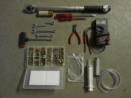
- wrench and 19mm socket to remove the left rear wheel, and torque wrench to put the wheel back on (lug nuts torque @ 130Nm each).
- 8 mm socket to remove the left rear fender liner fastener screws (and now is a good time to renew those old bad looking screws with nice plated ones...).
- 7 mm wrench for the bleeder valve on the PSD solonoid cylinder.
- 11 mm wrench and one very short 11 mm wrench for the bleeder valve on the differential (I made one by cutting a normal length one in half)
- flat screwdrivers so to be able to remove the four (4) plastic snap-on's of the left rear fender liner
- 1 meter of 5 mm (or 6 mm, I am not sure anymore) interior diameter flexible clear tubing to fit over the bleeder valves fittings.
- small and large syringes for being able to remove old fluid and pump in new fluid.
- box-cutter for cutting tie-wraps
- tie-wraps of small to medium length
- multimeter to measure resistance and voltage.
Not shown AND also needed:
- jack and jack stands to lift and support the rear of the car.
- front wheel chokes
- safety glasses: absolutely DO WEAR these when doing the flushing procedure! Do NOT risk getting break fluid into your eyes (which worse case might be under great pressure)!
- 10mm or 12/13 mm wrench for opening up the black plastic cover in the wheel well, behind which the PSD-unit relay and it's 30-amp fuse lives.
- 30-amp fuse(s)
- catch bottle to hold the old brake fluid. I used an old plastic drink bottle and made a hole through it's cap through which the clear-tubing goes.
- 1 liter of new brake fluid (e.g. Castrol GT LMA DOT 4.)
- rags for cleaning up the PSD-unit reservoir and catching any possible brake fluid splil's (note: brake fluid eats your expensive car paint in seconds!)
- working gloves
V. Preparations:
1. Read Louis Ott and John Veninger "PSD FLUID FLUSHING PROCEDURE", as it also contains several good pictures and explanations of the various parts of the PSD-unit. That way you know exactly what you are looking for and at.
2. Loosen the left rear wheel lug nuts enough, so that it will be easy enough to loosen them completely as per step 4.
3. Choke the front wheels of the car, and then safely jack up the rear of the car and support it on jack stands.
4. Further loosen the left rear wheel lug nuts and remove the left rear wheel (I usually positioning removed wheels strategically under the car, so that if for whatever reason a jack stand fails I will not).
VI. Procedure steps with photo's:
01. Have all your tools at the ready.
02. In the rear wheel well, remove the black plastic cover nut (it either takes a 10 or 12/13 mm wrench). Remove the black plastic cover so to reveal the PSD-unit relais and 30-amp fuse. Remove the fuse and measure it: it is most likely broken.
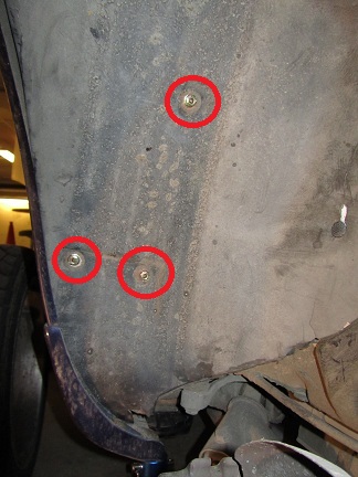
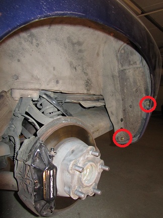
03. Remove the rear left fender liner by using your 8 mm socket: 3 screws on the left, as market with red circles.
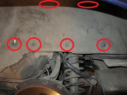
04. Remove the 4 plastic snap-on in the middle of the rear left fender liner as well as the 2 screws on the top, as marked with red circles and ovals.
05. Remove the 2 screws on the right, as market with red circles.
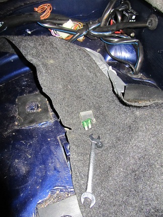
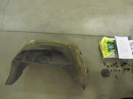
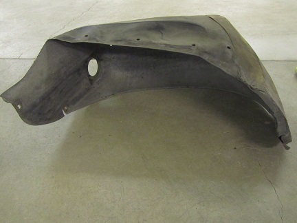
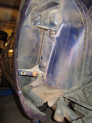
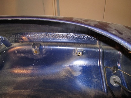
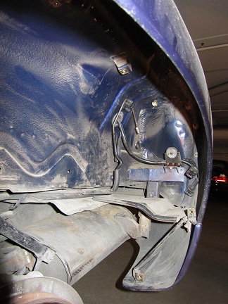
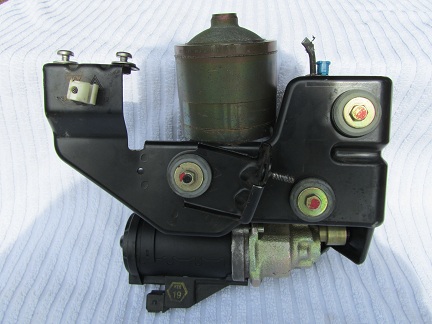
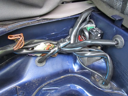
06-11. Very carefully remove the rear left fender liner, as it is made of very weak materials. The plastic it far too thin and does not hold up at all over the years (and these costs over US$ 500+ each!)...
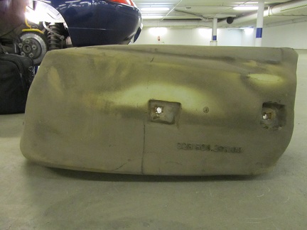
Note that the last photo shows the old PSD-unit removed, but at this stage we are not yet that far! Good for observing where and how the 3rd PSD-unit screw is positioned.
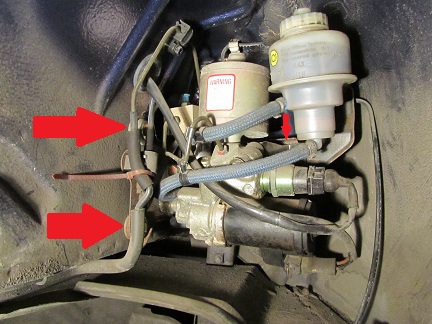
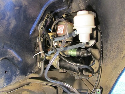
12. The PSD-unit is hold up by three (3) 10 mm screws: two (2) on the left hand side and one (1)...in the back (on from underneath, but I did not had the right tools to reach it that way)! See the red arrows, and the one (1) in the back is not the easiest to get too (what were they thinking...).
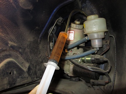
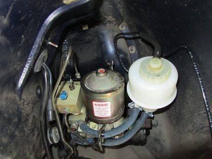
13. Carefully remove as much brake fluid as possible from the reservoir, using a syringe and short tubing.
- What is NOT shown is that the next step is to remove the hard metal "brake-line" from the top of the PSD-unit.
- To make sure there is NO pressure in the system, you can remove the blue-coloured cap of the bleeder valve and put clear-tubing onto it that goes to the catch-bottle.
- Open up the bleeder valve with the 7 mm wrench by at least 1/4 turn and see if any old fluid comes out. Do so VERY VERY slowly, in case there is still pressure in the PSD-unit!!!
- Once all fluid is out, or about none coming out to start with (which will be case if the PSD-unit has not been working for years, as then there is no pressure in the system anymore), then slowly remove the hard metal "brake-line" from the top of the PSD-unit.
13a. Although this is a picture from the new PSD-unit being re-installed (as per step 31), it shows where to put the 10 mm wrench for the 3rd screw if you remove it similarly like I did.

More to come...
I. Acknowledgements:
1. Hacker-Pschorr: for providing upfront permission to me (many months ago, writing this procedure out is way overdue by me!) of informing about the next line (to which I have no affiliation, just being a very happy customer!).
2. Harald Stein, who is THE expert in PSD-unit repairs and the person to go to if you live in Europe. More information on Harald's web-site:
http://www.stein-aviation.de/html/psd_engl.html
3. Louis Ott and John Veninger, for their documented "PSD FLUID FLUSHING PROCEDURE" write up (as for example stored here: http://www.928intl.com/repair/psd1.pdf )
4. Dwayne: for the always incredible amount of details in his write up's for this 928 community, and thereby being my inspiration for doing this procedure write up.
II. What is the problem:
1. When the PSD-unit (as standard on all 1990 and onwards 928) is not regularly serviced every 2 years by flushing the PSD hydraulic (brake)fluid, sooner or later the pump will seize up. Once the pump is fully seized up, then sooner or later the pump electric coils will overheat and then either melt through or short circuit - resulting into a fully broken pump.
2. The nasty bit is, that the PSD green light on your dashboard will still function fine whenever the PSD-unit should be coming into action and when you use a diagnostic tool (Bosch Hammer or one of the other tools) the PSD-unit might not have any alarm/problem state. So it appears all is OK, but it is not.
3. Of course a simple way to really test if your PSD-unit is functioning is to find a place with large amount of gravel and start driving - either stop-start drive away or circle/donuts. You'll know when it works!
4.In my case I knew when purchasing my 928 that there was something wrong with the PSD-unit, as the PO had informed me so upfront before even doing my PPI on the car (it was the only thing that was wrong with it). It had not been working for 2+ years before I started on my quest of getting it fixed.
III. What will become a side problem, when you fully remove your faulty old PSD-unit:
1. When the Solonoid Valve connector is disconnected from the PSD-unit, the combined ABS-PSD electronic unit will stop working and register a fault on your dashboard diagnostic display.
2. This will be fixed once you have your new/reconditioned PSD-unit installed, or in the case that such is going to take many weeks/months: I believe that you can work-around it by connecting a 2.7 ohm / 5 watt resistor to the Solonoid Valve connector. I believe this to be the case, as per my previous listing as per: https://rennlist.com/forums/9118081-post4.html . However: I have not done this yet, so thus far only my theory and not fully fact yet (I will proof it the next time I will need to flush my PSD-unit fluid, which is due in July 2014).
3. As long as it is not fixed, your ABS will not work so do drive and brake extra carefully during that time (I drove a few weeks like that, and all was fine)!
IV. Tools:
You will need the following tools:
- wrench and 19mm socket to remove the left rear wheel, and torque wrench to put the wheel back on (lug nuts torque @ 130Nm each).
- 8 mm socket to remove the left rear fender liner fastener screws (and now is a good time to renew those old bad looking screws with nice plated ones...).
- 7 mm wrench for the bleeder valve on the PSD solonoid cylinder.
- 11 mm wrench and one very short 11 mm wrench for the bleeder valve on the differential (I made one by cutting a normal length one in half)
- flat screwdrivers so to be able to remove the four (4) plastic snap-on's of the left rear fender liner
- 1 meter of 5 mm (or 6 mm, I am not sure anymore) interior diameter flexible clear tubing to fit over the bleeder valves fittings.
- small and large syringes for being able to remove old fluid and pump in new fluid.
- box-cutter for cutting tie-wraps
- tie-wraps of small to medium length
- multimeter to measure resistance and voltage.
Not shown AND also needed:
- jack and jack stands to lift and support the rear of the car.
- front wheel chokes
- safety glasses: absolutely DO WEAR these when doing the flushing procedure! Do NOT risk getting break fluid into your eyes (which worse case might be under great pressure)!
- 10mm or 12/13 mm wrench for opening up the black plastic cover in the wheel well, behind which the PSD-unit relay and it's 30-amp fuse lives.
- 30-amp fuse(s)
- catch bottle to hold the old brake fluid. I used an old plastic drink bottle and made a hole through it's cap through which the clear-tubing goes.
- 1 liter of new brake fluid (e.g. Castrol GT LMA DOT 4.)
- rags for cleaning up the PSD-unit reservoir and catching any possible brake fluid splil's (note: brake fluid eats your expensive car paint in seconds!)
- working gloves
V. Preparations:
1. Read Louis Ott and John Veninger "PSD FLUID FLUSHING PROCEDURE", as it also contains several good pictures and explanations of the various parts of the PSD-unit. That way you know exactly what you are looking for and at.
2. Loosen the left rear wheel lug nuts enough, so that it will be easy enough to loosen them completely as per step 4.
3. Choke the front wheels of the car, and then safely jack up the rear of the car and support it on jack stands.
4. Further loosen the left rear wheel lug nuts and remove the left rear wheel (I usually positioning removed wheels strategically under the car, so that if for whatever reason a jack stand fails I will not).
VI. Procedure steps with photo's:
01. Have all your tools at the ready.
02. In the rear wheel well, remove the black plastic cover nut (it either takes a 10 or 12/13 mm wrench). Remove the black plastic cover so to reveal the PSD-unit relais and 30-amp fuse. Remove the fuse and measure it: it is most likely broken.
03. Remove the rear left fender liner by using your 8 mm socket: 3 screws on the left, as market with red circles.
04. Remove the 4 plastic snap-on in the middle of the rear left fender liner as well as the 2 screws on the top, as marked with red circles and ovals.
05. Remove the 2 screws on the right, as market with red circles.
06-11. Very carefully remove the rear left fender liner, as it is made of very weak materials. The plastic it far too thin and does not hold up at all over the years (and these costs over US$ 500+ each!)...
Note that the last photo shows the old PSD-unit removed, but at this stage we are not yet that far! Good for observing where and how the 3rd PSD-unit screw is positioned.
12. The PSD-unit is hold up by three (3) 10 mm screws: two (2) on the left hand side and one (1)...in the back (on from underneath, but I did not had the right tools to reach it that way)! See the red arrows, and the one (1) in the back is not the easiest to get too (what were they thinking...).
13. Carefully remove as much brake fluid as possible from the reservoir, using a syringe and short tubing.
- What is NOT shown is that the next step is to remove the hard metal "brake-line" from the top of the PSD-unit.
- To make sure there is NO pressure in the system, you can remove the blue-coloured cap of the bleeder valve and put clear-tubing onto it that goes to the catch-bottle.
- Open up the bleeder valve with the 7 mm wrench by at least 1/4 turn and see if any old fluid comes out. Do so VERY VERY slowly, in case there is still pressure in the PSD-unit!!!
- Once all fluid is out, or about none coming out to start with (which will be case if the PSD-unit has not been working for years, as then there is no pressure in the system anymore), then slowly remove the hard metal "brake-line" from the top of the PSD-unit.
13a. Although this is a picture from the new PSD-unit being re-installed (as per step 31), it shows where to put the 10 mm wrench for the 3rd screw if you remove it similarly like I did.
More to come...
 03-04-2012, 05:19 PM
#2
Rennlist Member
Thread Starter
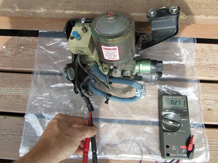
14-16. Remove all the three (3) electrical connectors, and then remove the 2 left side screws. Remove the old PSD-unit (it takes a bit of manouvering, be patient).
17. This shows me measuring the old PSD-unit solenoid, which shows 2.7 ohm and is within spec.
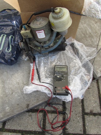
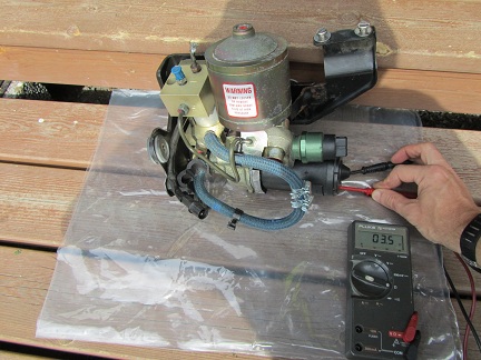
18. This shows me measuring the old PSD-unit pump coils, which shows 0.6 ohm meaning short circuit = fried...
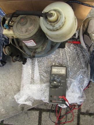
19. Because you have now removed the PSD-unit and thereby disconnected the solenoid connector resulting into an open circuit for the combined ABS-PSD electronic unit on this: the next time you will start your car you will get an ABS failure warning.
20. Obviously you already had the PSD failure warning, or if not then you now will have that too.
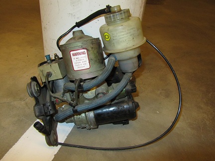
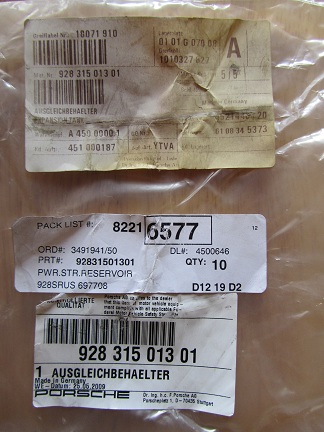
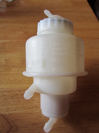
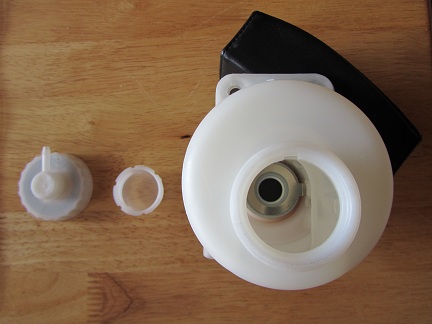
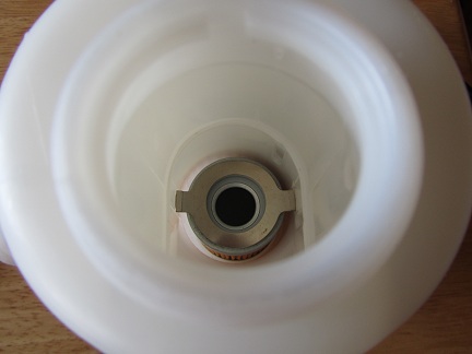
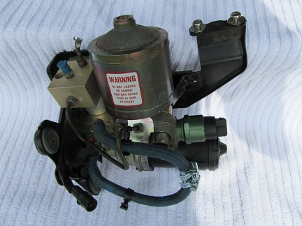
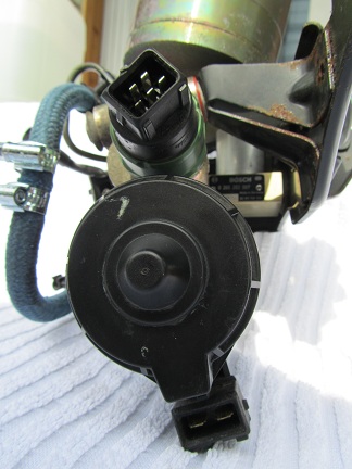
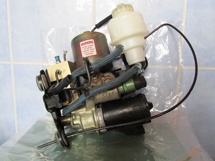
21-24. This shows the new reservoir and the fact that is has a build in filter (which can not be exchanged, bummer...). Harald was so kind to provide me a new one as part of the PSD-unit swap deal we agreed upon.
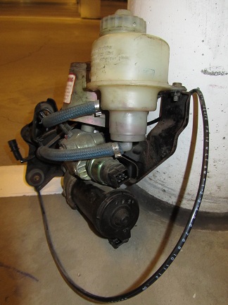
25-26. And this is the fully reconditioned and 2 year warranted swapped out PSD-unit. Solenoid shows 2.7 ohm and the pump shows 3.5 ohm (both good, obviously).
More to follow...
17. This shows me measuring the old PSD-unit solenoid, which shows 2.7 ohm and is within spec.
18. This shows me measuring the old PSD-unit pump coils, which shows 0.6 ohm meaning short circuit = fried...
19. Because you have now removed the PSD-unit and thereby disconnected the solenoid connector resulting into an open circuit for the combined ABS-PSD electronic unit on this: the next time you will start your car you will get an ABS failure warning.
20. Obviously you already had the PSD failure warning, or if not then you now will have that too.
21-24. This shows the new reservoir and the fact that is has a build in filter (which can not be exchanged, bummer...). Harald was so kind to provide me a new one as part of the PSD-unit swap deal we agreed upon.
25-26. And this is the fully reconditioned and 2 year warranted swapped out PSD-unit. Solenoid shows 2.7 ohm and the pump shows 3.5 ohm (both good, obviously).
More to follow...
03-04-2012, 05:32 PM
#3
Rennlist Member
Thread Starter
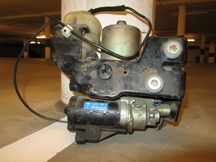
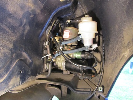
27-29. Various views of the reconditioned PSD-unit.
30. New reservoir fitted and hoses connected with provided clamps.
31. Reconditioned PSD-unit re-installed, starting with the back screw using a 10 mm wrench. When done, you need to bend the PSD-unit back a bit (via the back bracket) so to line it up for the two (2) screws on the left hand side.
32. Both two (2) left screws put in place, and the "brake-pipe" reconnected too. New (white) tie-wrap put in place as well, as is needed to keep it all on it's place.
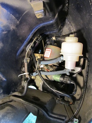
33. Replace the 30-amp fuse in the spare wheel well of the PSD-unit relay & fuse combo. I also put some foam underneath it as mentioned by other Rennlister's, so there is no possibility of any wires making short circuit with the ground of the car.
34. NOT shown: fill up the new reservoir with new brake fluid.
- And then it is time to follow the PSD-unit flush procedure, using your favorite tools (Bosch hammer or other 928 diagnostic tools as available, or as per Louis Ott and John Veninger write up).
- Here you can see the old fluid being pumped out just passed the solonoid lock valve from the bleeder screw (opened up at least 1/4 turn, and then I used a 928 diagnostic tool to start this 1st part of the flush procedure).
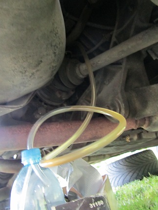
35. Once done with step 34 and that part all closed up again, hereby a close up of where the bleeder valve is on the differential.
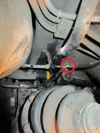
36. Clear tubing connected on the bleed screw.
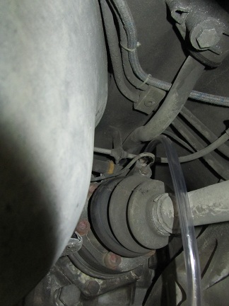
37. And this is where I needed the very short 11 mm wrench, to open up this particular bleeder valve at least 1/4 turn.
Here you can see the old fluid being pumped out (really mucky! I used a 928 diagnostic tool to start this 2nd part of the flush procedure).
38. Make sure to check that the reservoir is topped up with brake fluid to the max-mark.
39. Closing everything up.
- Be extra careful with reinstalling the super weak rear left fender liner (I have bits falling of by simply touching it...).
- Reinstall the wheel, lower the car and do the final torque on each lug nuts @ 130Nm each.
- Remove the front wheel chokes.
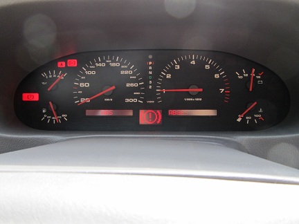
40. Key in the ignition: all warning light on as they should.
41. Pressed the brake so to check that it's warning light goes out - as it does.
More to follow...
30. New reservoir fitted and hoses connected with provided clamps.
31. Reconditioned PSD-unit re-installed, starting with the back screw using a 10 mm wrench. When done, you need to bend the PSD-unit back a bit (via the back bracket) so to line it up for the two (2) screws on the left hand side.
32. Both two (2) left screws put in place, and the "brake-pipe" reconnected too. New (white) tie-wrap put in place as well, as is needed to keep it all on it's place.
33. Replace the 30-amp fuse in the spare wheel well of the PSD-unit relay & fuse combo. I also put some foam underneath it as mentioned by other Rennlister's, so there is no possibility of any wires making short circuit with the ground of the car.
34. NOT shown: fill up the new reservoir with new brake fluid.
- And then it is time to follow the PSD-unit flush procedure, using your favorite tools (Bosch hammer or other 928 diagnostic tools as available, or as per Louis Ott and John Veninger write up).
- Here you can see the old fluid being pumped out just passed the solonoid lock valve from the bleeder screw (opened up at least 1/4 turn, and then I used a 928 diagnostic tool to start this 1st part of the flush procedure).
35. Once done with step 34 and that part all closed up again, hereby a close up of where the bleeder valve is on the differential.
36. Clear tubing connected on the bleed screw.
37. And this is where I needed the very short 11 mm wrench, to open up this particular bleeder valve at least 1/4 turn.
Here you can see the old fluid being pumped out (really mucky! I used a 928 diagnostic tool to start this 2nd part of the flush procedure).
38. Make sure to check that the reservoir is topped up with brake fluid to the max-mark.
39. Closing everything up.
- Be extra careful with reinstalling the super weak rear left fender liner (I have bits falling of by simply touching it...).
- Reinstall the wheel, lower the car and do the final torque on each lug nuts @ 130Nm each.
- Remove the front wheel chokes.
40. Key in the ignition: all warning light on as they should.
41. Pressed the brake so to check that it's warning light goes out - as it does.
More to follow...
03-04-2012, 05:35 PM
#4
Rennlist Member
Thread Starter
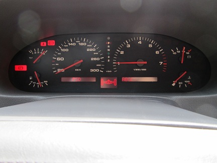
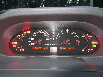
42. Starting the car: NO ABS and NO PSD warnings anymore, and a fully functional PSD-unit!
You are done, go for a fun drive!
Comments and improvements to this procedure very welcomed.
You are done, go for a fun drive!
Comments and improvements to this procedure very welcomed.
 Thank you very much. Beer on me if we ever meet
  03-04-2012, 09:02 PM
#6
Burning Brakes
Fantastic. My PSD appears to be operating correctly, but I have no idea when it was last serviced. This encourages me to try it myself...
Of course, I have to wait until Jerry finishes the fab of the replacement rear wheel liners... I dare not touch mine. I'm sure they will crumble!
Of course, I have to wait until Jerry finishes the fab of the replacement rear wheel liners... I dare not touch mine. I'm sure they will crumble!
03-05-2012, 10:02 PM
#7
Administrator - "Tyson"
Lifetime Rennlist
Member
Lifetime Rennlist
Member
Nice write-up!!!
Trending Topics
04-19-2012, 08:52 PM
#8
Rennlist Member
I thought I would append Arnoud�s excellent write-up with a few more pictures for those who may search on this topic when their PSD fails. Unfortunately, unlike Arnoud, my PSD woes were not solved after the rebuild. Doing the Ott/Vettinger flush, I had to stop at section IV, flushing the PSD slave cylinder as I was not getting fluid from the slave cylinder�s bleeder valve. I disconnected the line to the slave cylinder, cycled the PSD a couple times but was still not getting fluid to it. I then disconnected the line right before the pressure valve and fluid was flowing fine. In the end, in addition to a �train wreck� PSD unit, I also had a clogged pressure valve and a dry-rotted slave cylinder.
I need to thank Arnoud for hooking me up with Harald Stein who rebuilt my PSD. The price is significantly cheaper than new and he has a 2-year warranty. He lives in Germany and speaks excellent English. His website is at: http://www.stein-aviation.de/html/psd_engl.html. From the day I took it to DHL to send it to him, I had it back in 1 week!
Here�s what Harald said about my repair: �The pump was seized and had to be replaced, also the small pistons inside. Due to the seized pump the motor was burned and also had to be replaced.
Then there is a one way restrictor valve that was also blocked and replaced. The regulation valve was cleaned and is working fine, also the pressure reservoir is back to work again. The pressure switch was cleaned up and is working again. The reservoir was cleaned and the blocked and dirty filter removed (still no new units available). The complete unit was tested and is working perfect now.�
If a picture is worth a thousand words, below are 10,000. Note the PSD now has an external filter until new ones are made�it works fine; and who knows, I may just leave it this way and simply replace the filter every 2 years.
The guy who finds a suitable rebuild kit for the slave cylinder is going to make us all very happy. You don�t even want to know how much a new one is� but if you ever need the part numbers, the pressure valve is 928 315 211 03 and the slave cylinder is 928 332 775 09.
Thanks again Arnoud!
Last edited by NoVector; 09-09-2018 at 12:49 AM.
04-20-2012, 01:32 AM
#11
Archive Gatekeeper
Rennlist Member
Rennlist Member
Those green seals look reminiscent of the teflon seals Ferraris use on the tranny input shaft:
http://www.ricambiamerica.com/produc...ucts_id=198181
I'm sure ours are a different size but maybe the same ballpark?
This link lists the types of seal compounds that are compatible with brake fluid- EPDM, SBR, and filled PTFE. Just to narrow things down a bit..
http://www.dkirubber.com/materials.asp
04-20-2012, 02:27 AM
#12
Rennlist Member
Thread Starter
Thanks towards Bruce for immediatelly adding your findings & detailed photo's to it and taking the whole thread to the next level!
It thereby also shows to all of us who have PSD why the regular 2-yearly flushing is so important to do: continue to neglect it and the pile of parts getting broken accumulates quickly...
Rob: interesting find about those green seals, thanks for sharing and making us aware.
It thereby also shows to all of us who have PSD why the regular 2-yearly flushing is so important to do: continue to neglect it and the pile of parts getting broken accumulates quickly...
Rob: interesting find about those green seals, thanks for sharing and making us aware.
Those green seals look reminiscent of the teflon seals Ferraris use on the tranny input shaft:
http://www.ricambiamerica.com/produc...ucts_id=198181
I'm sure ours are a different size but maybe the same ballpark?
This link lists the types of seal compounds that are compatible with brake fluid- EPDM, SBR, and filled PTFE. Just to narrow things down a bit..
http://www.dkirubber.com/materials.asp
http://www.ricambiamerica.com/produc...ucts_id=198181
I'm sure ours are a different size but maybe the same ballpark?
This link lists the types of seal compounds that are compatible with brake fluid- EPDM, SBR, and filled PTFE. Just to narrow things down a bit..
http://www.dkirubber.com/materials.asp
04-20-2012, 02:32 AM
#13
Archive Gatekeeper
Rennlist Member
Rennlist Member
Arnoud:
I haven't actually 'found' anything, just spouting utter conjecture. as I am prone to doing . But I did learn something tonight about seal materials and construction. I have a spare PSD slave cylinder here- if they can be opened non-destructively perhaps I'll pull and measure a seal to get some dimensions.
I haven't actually 'found' anything, just spouting utter conjecture. as I am prone to doing
. But I did learn something tonight about seal materials and construction. I have a spare PSD slave cylinder here- if they can be opened non-destructively perhaps I'll pull and measure a seal to get some dimensions.
04-20-2012, 03:30 AM
#14
Rennlist Member
I opened mine by first removing the snap-ring, the washer and center shaft fall right out. I soaked the barrel of the cylinder with Dot 4 fluid overnight to "loosen things up." The following day, I used a little rubber hose with one end connected to my compressor's air gun and the other stuffed in the end of the slave cylinder--where the feed line goes. A little puff of air and the guts popped right out. Maybe it could be done with a strong magnet and just pull the center out too. Not sure. But I think you're right about the material--the green rings are not soft like rubber--they're hard like nylon/teflon.
Last edited by NoVector; 09-09-2018 at 12:49 AM.
01-04-2017, 03:18 PM
#15
Rennlist Member
Join Date: Feb 2011
Location: Mostly in my workshop located in Sweden.
Posts: 2,226
Received 442 Likes
on
244 Posts
Lengthy write up, with 42 photo's in all. If you need a high res picture of any of these, then PM me.
I. Acknowledgements:
1. Hacker-Pschorr: for providing upfront permission to me (many months ago, writing this procedure out is way overdue by me!) of informing about the next line (to which I have no affiliation, just being a very happy customer!).
2. Harald Stein, who is THE expert in PSD-unit repairs and the person to go to if you live in Europe. More information on Harald's web-site:
http://www.stein-aviation.de/html/psd_engl.html
3. Louis Ott and John Veninger, for their documented "PSD FLUID FLUSHING PROCEDURE" write up (as for example stored here: http://www.928intl.com/repair/psd1.pdf )
4. Dwayne: for the always incredible amount of details in his write up's for this 928 community, and thereby being my inspiration for doing this procedure write up.
II. What is the problem:
1. When the PSD-unit (as standard on all 1990 and onwards 928) is not regularly serviced every 2 years by flushing the PSD hydraulic (brake)fluid, sooner or later the pump will seize up. Once the pump is fully seized up, then sooner or later the pump electric coils will overheat and then either melt through or short circuit - resulting into a fully broken pump.
2. The nasty bit is, that the PSD green light on your dashboard will still function fine whenever the PSD-unit should be coming into action and when you use a diagnostic tool (Bosch Hammer or one of the other tools) the PSD-unit might not have any alarm/problem state. So it appears all is OK, but it is not.
3. Of course a simple way to really test if your PSD-unit is functioning is to find a place with large amount of gravel and start driving - either stop-start drive away or circle/donuts. You'll know when it works!
4.In my case I knew when purchasing my 928 that there was something wrong with the PSD-unit, as the PO had informed me so upfront before even doing my PPI on the car (it was the only thing that was wrong with it). It had not been working for 2+ years before I started on my quest of getting it fixed.
III. What will become a side problem, when you fully remove your faulty old PSD-unit:
1. When the Solonoid Valve connector is disconnected from the PSD-unit, the combined ABS-PSD electronic unit will stop working and register a fault on your dashboard diagnostic display.
2. This will be fixed once you have your new/reconditioned PSD-unit installed, or in the case that such is going to take many weeks/months: I believe that you can work-around it by connecting a 2.7 ohm / 5 watt resistor to the Solonoid Valve connector. I believe this to be the case, as per my previous listing as per: https://rennlist.com/forums/9118081-post4.html . However: I have not done this yet, so thus far only my theory and not fully fact yet (I will proof it the next time I will need to flush my PSD-unit fluid, which is due in July 2014).
3. As long as it is not fixed, your ABS will not work so do drive and brake extra carefully during that time (I drove a few weeks like that, and all was fine)!
IV. Tools:
You will need the following tools:
Attachment 613371
- wrench and 19mm socket to remove the left rear wheel, and torque wrench to put the wheel back on (lug nuts torque @ 130Nm each).
- 8 mm socket to remove the left rear fender liner fastener screws (and now is a good time to renew those old bad looking screws with nice plated ones...).
- 7 mm wrench for the bleeder valve on the PSD solonoid cylinder.
- 11 mm wrench and one very short 11 mm wrench for the bleeder valve on the differential (I made one by cutting a normal length one in half)
- flat screwdrivers so to be able to remove the four (4) plastic snap-on's of the left rear fender liner
- 1 meter of 5 mm (or 6 mm, I am not sure anymore) interior diameter flexible clear tubing to fit over the bleeder valves fittings.
- small and large syringes for being able to remove old fluid and pump in new fluid.
- box-cutter for cutting tie-wraps
- tie-wraps of small to medium length
- multimeter to measure resistance and voltage.
Not shown AND also needed:
- jack and jack stands to lift and support the rear of the car.
- front wheel chokes
- safety glasses: absolutely DO WEAR these when doing the flushing procedure! Do NOT risk getting break fluid into your eyes (which worse case might be under great pressure)!
- 10mm or 12/13 mm wrench for opening up the black plastic cover in the wheel well, behind which the PSD-unit relay and it's 30-amp fuse lives.
- 30-amp fuse(s)
- catch bottle to hold the old brake fluid. I used an old plastic drink bottle and made a hole through it's cap through which the clear-tubing goes.
- 1 liter of new brake fluid (e.g. Castrol GT LMA DOT 4.)
- rags for cleaning up the PSD-unit reservoir and catching any possible brake fluid splil's (note: brake fluid eats your expensive car paint in seconds!)
- working gloves
V. Preparations:
1. Read Louis Ott and John Veninger "PSD FLUID FLUSHING PROCEDURE", as it also contains several good pictures and explanations of the various parts of the PSD-unit. That way you know exactly what you are looking for and at.
2. Loosen the left rear wheel lug nuts enough, so that it will be easy enough to loosen them completely as per step 4.
3. Choke the front wheels of the car, and then safely jack up the rear of the car and support it on jack stands.
4. Further loosen the left rear wheel lug nuts and remove the left rear wheel (I usually positioning removed wheels strategically under the car, so that if for whatever reason a jack stand fails I will not).
VI. Procedure steps with photo's:
01. Have all your tools at the ready.
Attachment 613371
02. In the rear wheel well, remove the black plastic cover nut (it either takes a 10 or 12/13 mm wrench). Remove the black plastic cover so to reveal the PSD-unit relais and 30-amp fuse. Remove the fuse and measure it: it is most likely broken.
Attachment 613372
03. Remove the rear left fender liner by using your 8 mm socket: 3 screws on the left, as market with red circles.
Attachment 613373
04. Remove the 4 plastic snap-on in the middle of the rear left fender liner as well as the 2 screws on the top, as marked with red circles and ovals.
Attachment 613374
05. Remove the 2 screws on the right, as market with red circles.
Attachment 613375
06-11. Very carefully remove the rear left fender liner, as it is made of very weak materials. The plastic it far too thin and does not hold up at all over the years (and these costs over US$ 500+ each!)...
Note that the last photo shows the old PSD-unit removed, but at this stage we are not yet that far! Good for observing where and how the 3rd PSD-unit screw is positioned.
Attachment 613376
Attachment 613377
Attachment 613378
Attachment 613379
Attachment 613380
Attachment 613381
12. The PSD-unit is hold up by three (3) 10 mm screws: two (2) on the left hand side and one (1)...in the back (on from underneath, but I did not had the right tools to reach it that way)! See the red arrows, and the one (1) in the back is not the easiest to get too (what were they thinking...).
Attachment 613382
13. Carefully remove as much brake fluid as possible from the reservoir, using a syringe and short tubing.
- What is NOT shown is that the next step is to remove the hard metal "brake-line" from the top of the PSD-unit.
- To make sure there is NO pressure in the system, you can remove the blue-coloured cap of the bleeder valve and put clear-tubing onto it that goes to the catch-bottle.
- Open up the bleeder valve with the 7 mm wrench by at least 1/4 turn and see if any old fluid comes out. Do so VERY VERY slowly, in case there is still pressure in the PSD-unit!!!
- Once all fluid is out, or about none coming out to start with (which will be case if the PSD-unit has not been working for years, as then there is no pressure in the system anymore), then slowly remove the hard metal "brake-line" from the top of the PSD-unit.
Attachment 613383
13a. Although this is a picture from the new PSD-unit being re-installed (as per step 31), it shows where to put the 10 mm wrench for the 3rd screw if you remove it similarly like I did.
Attachment 613396
More to come...
�ke

