
PWM dimmer for instrument backlighting after upgrading to LEDs


 10-14-2012, 08:33 PM
#47
Nordschleife Master
Cool thanks for bumping this thread - I keep meaning to ask Ed about these dimmers when I'm driving at night, and failing to do so when I'm at my computer.
10-14-2012, 08:51 PM
#48
Addict
Rennlist Member
Rennlist Member
Thread Starter
OK, I know it has been ages since I've provided an update on the status of this project. I've got bad news, lame excuses, and good news.
Bad News
Well, there's really only one bad news item: I'm not done with this. The dimmer module is not available yet. I'm really sorry about that.
Lame Excuses
I've have been crazy busy with a ton of obligations, both professional and personal, over the last however-many-I-lost-count months. More traveling than normal, associated preparation and follow-up, etc.
Good News
I'm still committed to getting this done, and I'm actually pretty close to being done. I have a final circuit design that I know works (I've had it working on a protoboard for quite some time) and have all the parts on hand with the exception of the printed circuit boards (PCBs). And that's the part I just need to finish off: the PCB design. I did one PCB design months ago, but I wasn't satisfied with it. I know exactly what I need now, and just need a few hours of uninterrupted time to get that done. Just haven't gotten that time.
What's also good is that I'm seeing an end to the stream of obligations that have been keeping me from getting back to this. So... I have every intention of resuming work on it within the next week or two.
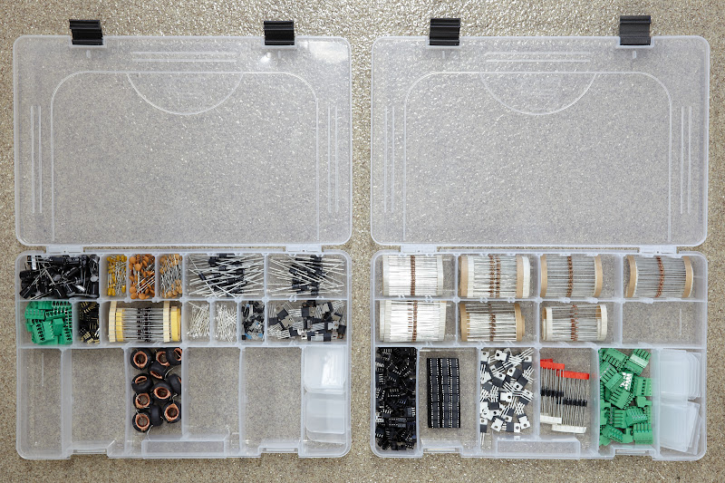
FWIW, here's a photo I just took of most of the parts, ready to go. I omitted some things (like the ABS enclosures, wires, and some terminals) that are in separate bags or boxes.
What to Expect When It's Finally Available
Here's what you should expect from the final product. No absolute promises that nothing will change, but I'm pretty sure about the following:
Regarding the use of through-hole components: I have chosen to use through-hole components rather than SMT components because it would allow this module to be sold as a DIY kit, too, for those who might want to assemble their own: it would just require soldering components to a PCB and very simple mechanical assembly (fitting the PCB into the plastic enclosure, etc.). At this point, I'd be interested to know if anyone would want to assemble their own, as it would influence what order I do a few last things (like whether or not I'd need an assembly manual or just an installation guide). This seems like a good idea to me, as if I don't provide this DIY option, I can see myself being the bottleneck on assembly, too.
If you plan on getting one of these modules and want to prepare wiring a little, run a ground wire (in "Porsche brown," of course) to where you'd want the dimmer module to live. I used the grounding point that's somewhere behind (and, IIRC, a little below) the instrument cluster; I had easy access to this when I had the instrument cluster out. If you find yourself with easy access to a grounding point like that, take advantage of it now and run that wire. Heck, you might even want to run another ground wire or two as spares for other uses. They're handy to have around.
Bad News
Well, there's really only one bad news item: I'm not done with this. The dimmer module is not available yet. I'm really sorry about that.
Lame Excuses
I've have been crazy busy with a ton of obligations, both professional and personal, over the last however-many-I-lost-count months. More traveling than normal, associated preparation and follow-up, etc.
Good News
I'm still committed to getting this done, and I'm actually pretty close to being done. I have a final circuit design that I know works (I've had it working on a protoboard for quite some time) and have all the parts on hand with the exception of the printed circuit boards (PCBs). And that's the part I just need to finish off: the PCB design. I did one PCB design months ago, but I wasn't satisfied with it. I know exactly what I need now, and just need a few hours of uninterrupted time to get that done. Just haven't gotten that time.
What's also good is that I'm seeing an end to the stream of obligations that have been keeping me from getting back to this. So... I have every intention of resuming work on it within the next week or two.
FWIW, here's a photo I just took of most of the parts, ready to go. I omitted some things (like the ABS enclosures, wires, and some terminals) that are in separate bags or boxes.

What to Expect When It's Finally Available
Here's what you should expect from the final product. No absolute promises that nothing will change, but I'm pretty sure about the following:
- The module will be in a 3.25" � 2.125" � 1.25" plastic (ABS) enclosure—the same enclosure used for the prototype shown back in post #27. (The guts will be way different, though. )
- The module won't have any special mounting tabs or anything—you'll just use one or two nylon zip ties to fasten it somewhere under the instrument pod.
- The final (I hope ) design is much more robust than the prototype in my car (which is still working, BTW): it can handle shorted output, reversed input power, brief voltage spikes on input power, etc.
- The module will require five connections as follows (and the kit will include whatever wire is needed and a terminal for the new ground wire):
- two wires to the car's original dimmer rheostat;
- two wires to the wires originally connected to the car's rheostat;
- and a new ground wire.
- The wiring you do on the car side will be terminated with a 5-terminal connector; the module will mate with this connector.
- Through-hole components are used rather than SMT (surface mount) components. See comments below for the rationale.
- The module is designed for 3 A maximum drive (at 12 VDC). My '90 928 S4 (with all instrument lighting provided by LEDs as described in Converting Porsche 928 Interior Lighting to LEDs) draws about 300 mA, i.e., about 10% of the maximum current that the dimmer module can provide.
- The module should work with any mix of incandescent and LED bulbs, although I'll admit that I haven't tested to see if the relative brightnesses between incandescent bulbs and LED bulbs is optimal in such a configuration.
- The module is designed for a dimmer rheostat that measures about 0 Ω at one end and around 4 Ω to 6 Ω at the other end. A few people have asked me whether this module will work for other cars; it probably will if they have a similar dimmer rheostat. I can provide alternative microcontroller software that would make it work with higher resistance rheostats, but lower resistance rheostats would require circuitry changes.
Regarding the use of through-hole components: I have chosen to use through-hole components rather than SMT components because it would allow this module to be sold as a DIY kit, too, for those who might want to assemble their own: it would just require soldering components to a PCB and very simple mechanical assembly (fitting the PCB into the plastic enclosure, etc.). At this point, I'd be interested to know if anyone would want to assemble their own, as it would influence what order I do a few last things (like whether or not I'd need an assembly manual or just an installation guide). This seems like a good idea to me, as if I don't provide this DIY option, I can see myself being the bottleneck on assembly, too.
If you plan on getting one of these modules and want to prepare wiring a little, run a ground wire (in "Porsche brown," of course) to where you'd want the dimmer module to live. I used the grounding point that's somewhere behind (and, IIRC, a little below) the instrument cluster; I had easy access to this when I had the instrument cluster out. If you find yourself with easy access to a grounding point like that, take advantage of it now and run that wire. Heck, you might even want to run another ground wire or two as spares for other uses. They're handy to have around.
Last edited by Ed Scherer; 11-16-2012 at 10:53 PM.
10-23-2012, 05:04 PM
#49
Rennlist Member
Thanks for your detailed update and your continued commitment on this PWM dimmer project, Ed!
Regarding your question if anyone would want to assemble their own: I would be interested in that, provided that you would not need to spend any significant amount of time on making an additional assembly manual.
Regarding your question if anyone would want to assemble their own: I would be interested in that, provided that you would not need to spend any significant amount of time on making an additional assembly manual.
11-16-2012, 10:52 PM
#51
Addict
Rennlist Member
Rennlist Member
Thread Starter
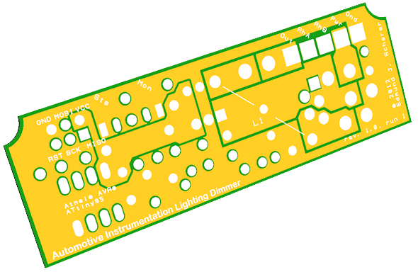
I finally got the PCB designed. This weekend I should be able to send off the design and get a few prototype boards fabricated and if they check out, I'll immediately reorder a big batch of production boards. Sorry this has taken so long, but the end is in sight.
The PCB is pretty small�3.1" � 1"�considering that it's going to be stuffed with through-hole components. It'll sit vertically in the 3.25" � 2.125" � 1.25" plastic (ABS) enclosure that I already showed back in post #27 (it just slides into the slots; no fasteners required).
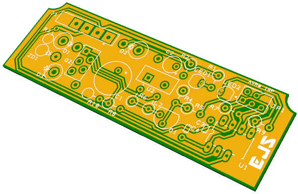
Here are 3D renderings of the top and bottom of the board (minus the components; I don't have good enough 3D models of the components to include them):
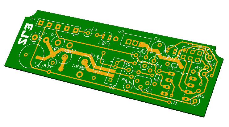
The PCB is pretty small�3.1" � 1"�considering that it's going to be stuffed with through-hole components. It'll sit vertically in the 3.25" � 2.125" � 1.25" plastic (ABS) enclosure that I already showed back in post #27 (it just slides into the slots; no fasteners required).
Here are 3D renderings of the top and bottom of the board (minus the components; I don't have good enough 3D models of the components to include them):
11-18-2012, 05:36 PM
#54
Addict
Rennlist Member
Rennlist Member
Thread Starter
Interesting that there's that much interest in DIYing it. That's great! I guess the only thing I'll need to do after the PCBs are manufactured and tested for those of you who want DIY kits is getting the holes drilled/bored in the plastic cases. I wouldn't expect you to have to do that yourself. The two for the round LEDs are easy (drill press), but the rectangular slot for the connector won't be so easy (I don't have any equipment for automating that).
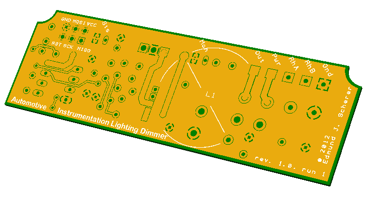
Anyway, I thought I was done with the PCB yesterday, but I made one more pass and this design is way better than what I had yesterday (copper pours for significant nets, much more copper where needed for significant current flow, etc.) and overall better routing. No vias at all! And only copper pours on the bottom side.
PCB design work is a serious time waster when you're a novice, but also OCD.
The bottom side rendering shows the solder mask and you don't see any individual pads or traces; there are just various copper pours for a few heavily used nets.
Last edited by Ed Scherer; 11-19-2012 at 10:44 AM.
11-18-2012, 06:28 PM
#56
Addict
Rennlist Member
Rennlist Member
Join Date: Oct 2003
Location: Gone. On the Open Road
Posts: 16,328
Received 1,543 Likes
on
1,007 Posts
I'll take three (non-DIY.)
12-03-2012, 01:40 AM
#57
Addict
Rennlist Member
Rennlist Member
Thread Starter
PCBs have shipped and should be here in a few days. Fingers crossed that the first batch will be usable.
A couple of weeks ago, I commented:
So... I got the enclosure—the little ABS (plastic) "speedy box"—figured out and have drafted my nephew to see if he can machine them to my specs; he's got a little desktop milling machine (a Taig MicroMill, FWIW) that should be able to do the job. I might just have to get one of those myself; I just checked his out yesterday, and I was surprised how compact it was.
Knowing that the enclosure openings will now be done by a CNC milling machine, I decided to do a nice design (IMHO) for them:
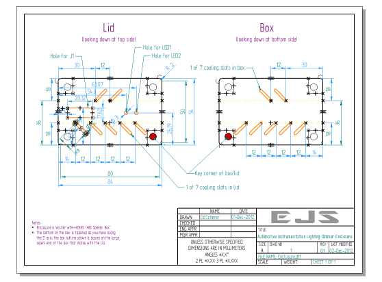
It was yet another challenge, as I needed to hunt down some appropriate CAD software and get up to speed (like I said, I've been away from this stuff for quite awhile...). Wound up using Solid Edge 2D. Pretty darn powerful (and consequently, not trivial to learn) for freely available software, IMHO.
That's still one step away from the milling machine, though; there's still some work in taking that design, importing it into CamBam (the CAM software used with that Taig CNC milling machine) and working out the CNC stuff, but... that won't be my problem (probably).
I'm having a blast with all of this, though, as it has been a great excuse for increasing my exposure to technical areas I just haven't had reason to explore for quite some time.
Also... once I get to the point where these are ready, I'll be figuring out the price (again, I'm not trying to make money on this; initially, at least, it'll just be parts cost plus shipping plus something for labor for the ones I assemble myself), re-contacting everyone who has expressed interest, providing updated information (like prices for DIY-assembly vs. already-assembled-and-ready-to-install, purchase information, etc.), and then taking it from there.
A couple of weeks ago, I commented:
I guess the only thing I'll need to do after the PCBs are manufactured and tested for those of you who want DIY kits is getting the holes drilled/bored in the plastic cases. I wouldn't expect you to have to do that yourself. The two for the round LEDs are easy (drill press), but the rectangular slot for the connector won't be so easy (I don't have any equipment for automating that).
Knowing that the enclosure openings will now be done by a CNC milling machine, I decided to do a nice design (IMHO) for them:
It was yet another challenge, as I needed to hunt down some appropriate CAD software and get up to speed (like I said, I've been away from this stuff for quite awhile...
). Wound up using Solid Edge 2D. Pretty darn powerful (and consequently, not trivial to learn) for freely available software, IMHO.That's still one step away from the milling machine, though; there's still some work in taking that design, importing it into CamBam (the CAM software used with that Taig CNC milling machine) and working out the CNC stuff, but... that won't be my problem (probably
).I'm having a blast with all of this, though, as it has been a great excuse for increasing my exposure to technical areas I just haven't had reason to explore for quite some time.
Also... once I get to the point where these are ready, I'll be figuring out the price (again, I'm not trying to make money on this; initially, at least, it'll just be parts cost plus shipping plus something for labor for the ones I assemble myself), re-contacting everyone who has expressed interest, providing updated information (like prices for DIY-assembly vs. already-assembled-and-ready-to-install, purchase information, etc.), and then taking it from there.
Last edited by Ed Scherer; 12-03-2012 at 02:01 AM.