Wiring Diagram Help
 07-26-2011, 10:06 PM
#1
Racer
Thread Starter
I have a couple of wiring diagram questions for those who are wisened in the ways of Porsche drafting.
1) On sector K83 of Sheet 10, there is a number of wires that go to a Box with "6" in the middle. What do these boxes mean? I have seen them elsewhere (e.g. there is a 1, 2, and 4 in boxes for the injector system)
2) On sector E90 of sheet 10, there is a common line labeled "30". There is also on F88 a line labeled "15". What do these lines mean...A common, a bolt, a wire splice, etc???
Thanks
- Matt
 07-26-2011, 10:29 PM
#2
Addict
Rennlist Member
Rennlist Member
I have a couple of wiring diagram questions for those who are wisened in the ways of Porsche drafting.
1) On sector K83 of Sheet 10, there is a number of wires that go to a Box with "6" in the middle. What do these boxes mean? I have seen them elsewhere (e.g. there is a 1, 2, and 4 in boxes for the injector system)
2) On sector E90 of sheet 10, there is a common line labeled "30". There is also on F88 a line labeled "15". What do these lines mean...A common, a bolt, a wire splice, etc???
Thanks
- Matt
1) On sector K83 of Sheet 10, there is a number of wires that go to a Box with "6" in the middle. What do these boxes mean? I have seen them elsewhere (e.g. there is a 1, 2, and 4 in boxes for the injector system)
2) On sector E90 of sheet 10, there is a common line labeled "30". There is also on F88 a line labeled "15". What do these lines mean...A common, a bolt, a wire splice, etc???
Thanks
- Matt
2) These are DIN 72552 / Bosch terminal/bus designations. "30" = "Line from battery positive terminal (direct)" and "15" = "Switch-controlled plus downstream from battery (from ignition switch)". The whole set of terminal designations are good to know, as you'll see them all over: on relay terminals, pod switches, etc.
07-26-2011, 10:33 PM
#3
Racer
Thread Starter
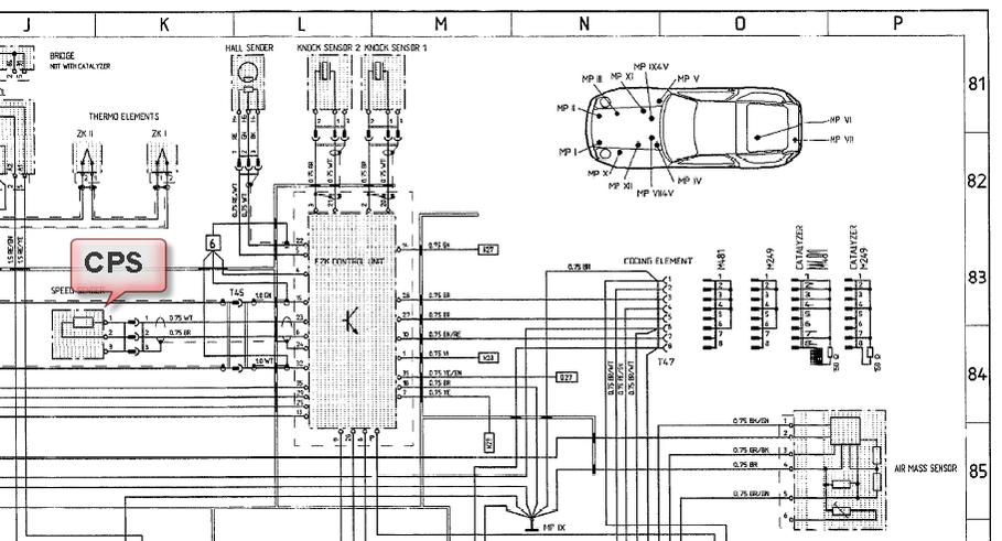
I am trying to chase the circuits from the CPS back to the EZK. I noticed that there is a connector at the end of the CPS pigtail, which is shown on the wiring diagram. Then there is another connector on the diagram "T45" (On Section K83 of the wiring diagram). The drawings state that this is at location 6dL, which appears to be on the passenger side of the car around the fuse panel.
DOes anyone know what this is?????
DOes anyone know what this is?????
07-26-2011, 10:38 PM
#4
Addict
Rennlist Member
Rennlist Member
I am trying to chase the circuits from the CPS back to the EZK. I noticed that there is a connector at the end of the CPS pigtail, which is shown on the wiring diagram. Then there is another connector on the diagram "T45" (On Section K83 of the wiring diagram). The drawings state that this is at location 6dL, which appears to be on the passenger side of the car around the fuse panel.
DOes anyone know what this is?????
DOes anyone know what this is?????
I'm not sure what you're asking, though "What this is". It's a two-pin connector, with one green wire and one white wire on each side.
 07-26-2011, 10:43 PM
#5
Racer
Thread Starter
Thanks. Does under central electric mean that it's behind the fuse panel?? It seems that there is a connector under the MAF at the end of the pigtail. then it seems from the descriptions that there is another connector behind the fuse panel??
 07-26-2011, 10:56 PM
#7
Rennlist Member
I am trying to chase the circuits from the CPS back to the EZK. I noticed that there is a connector at the end of the CPS pigtail, which is shown on the wiring diagram. Then there is another connector on the diagram "T45" (On Section K83 of the wiring diagram). The drawings state that this is at location 6dL, which appears to be on the passenger side of the car around the fuse panel.
Does anyone know what this is?????
Does anyone know what this is?????
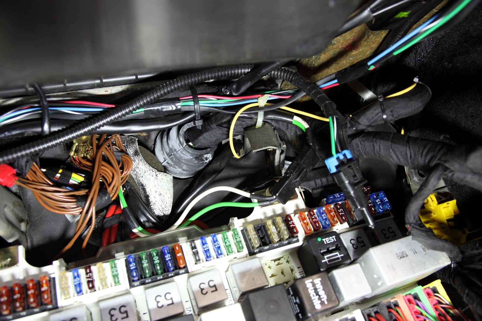
Matt, if you are looking for the CPS connection to the EZK, it is wired direct. The CPS ("speed sensor" on the wiring diagram) has a short pigtail and a (unlabeled) disconnect that lives in a bracket under the MAF, and then runs direct to the EZK through the engine harness-- no other disconnects.
The T45 disconnects are for the ignition-coil drivers, pins 15 & 32 on the EZK. Those do wander a bit...
P.S. Ed, that CE panel is really clean, have you been down there scrubbing???!!


Trending Topics
07-26-2011, 11:05 PM
#9
Rennlist Member
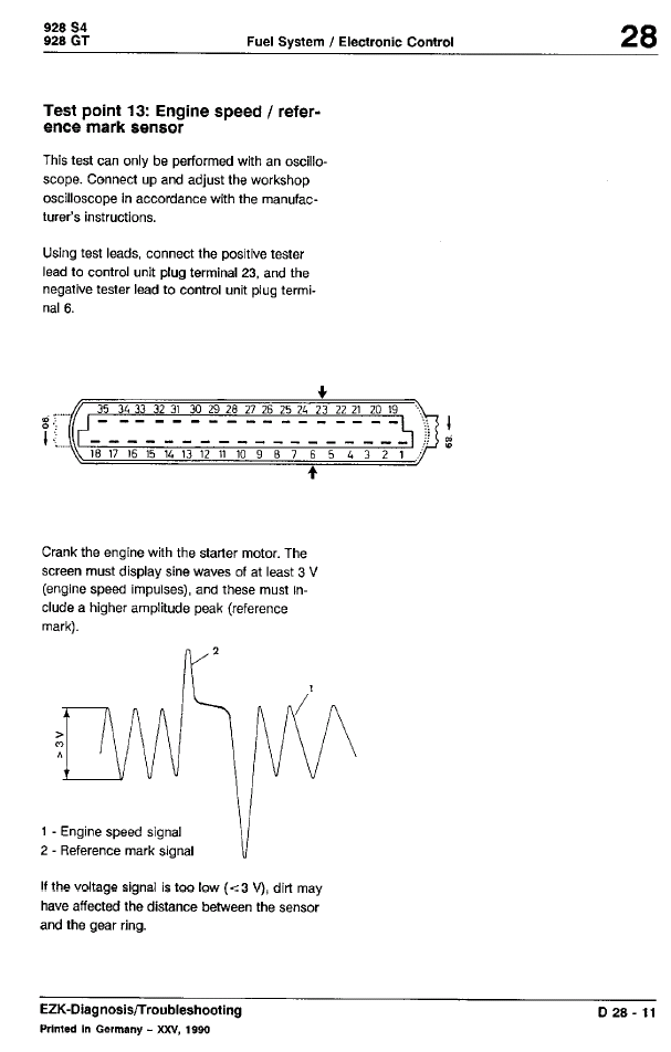
And no, I haven't had occasion to put a 'scope on a good one. I think you can do that from the EZK connector (there is a description in the WSM, section 24/28).
What are the symptoms?
07-26-2011, 11:05 PM
#10
Racer
Thread Starter
Jim thanks! I misread the diagram. I will tap into the EZP connectors to try and test the sine wave from the CPS. For the probe, do I connect the signal probe to pin 23, and the ground to pin 6 on the connector??
07-26-2011, 11:11 PM
#11
Rennlist Member