
Torque Tube, Torque Converter Bearing Replacement Procedure w/pics
 12-19-2010, 06:56 PM
#31
Rennlist Member
Thread Starter
Join Date: Sep 2007
Location: Ridgecrest, California
Posts: 1,363
Likes: 0
Received 143 Likes
on
28 Posts
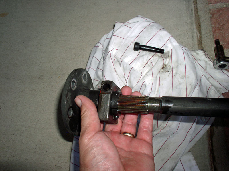
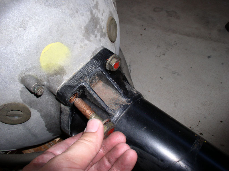
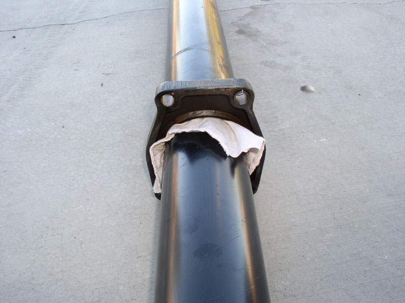
I fully removed the bolt and slid the clamp off the drive shaft splines as shown.
Next, remove the bolts that were temporarily installed to secure the bell housing to the TT and remove the bell housing.
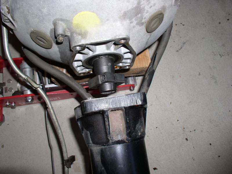
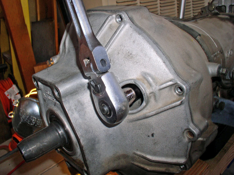
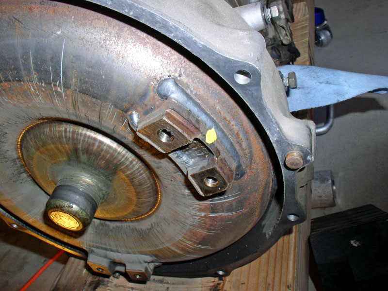
Loosen the four 19mm bolts that secure the TT to the TC housing as shown. Do not remove the bolts yet.
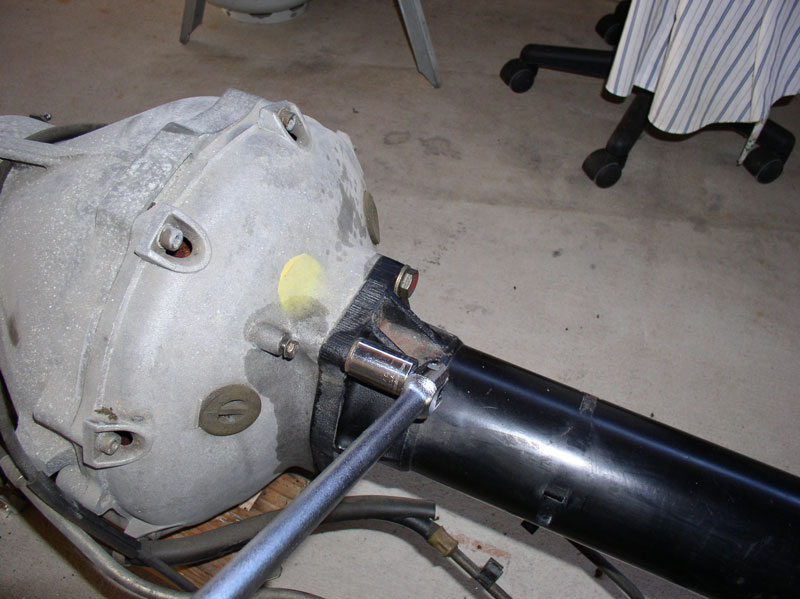
I supported the transmission and end of the TT so weight is evenly distributed along the TT and not causing the connection at the TC housing to bind.
I then removed the 4 previously loosened bolts.
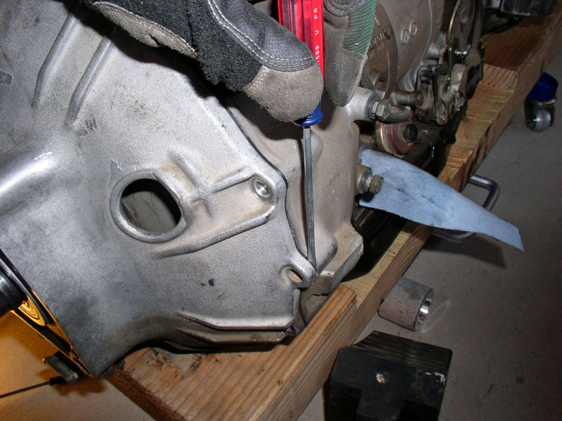
Once the bolts are removed, the TT will most likely remain attached to the TC housing due to the locating pins still being engaged. I then pulled on the TT with an up and down motion to break the TT free. If it’s being stubborn, you can use a thin flat bladed screwdriver to gently pry the TT away from the TC housing.
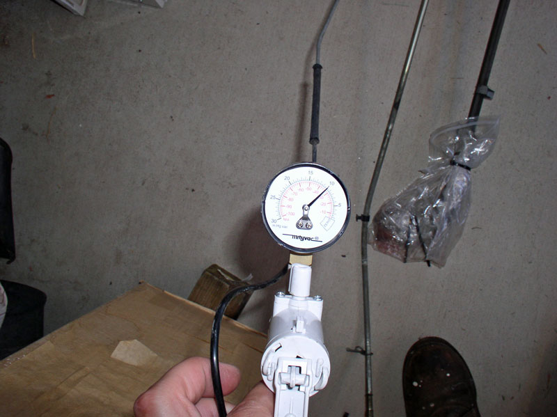
Once the TT is removed from the transmission, I tested the vacuum line to verify there were no leaks. If the line will not hold vacuum, check the connections and rubber hoses for leaks and replace, if needed. If the vacuum modulator on the transmission is not holding vacuum, it will need to be repaired. In my case, everything was sealed up and held vacuum with no drop after several minutes.
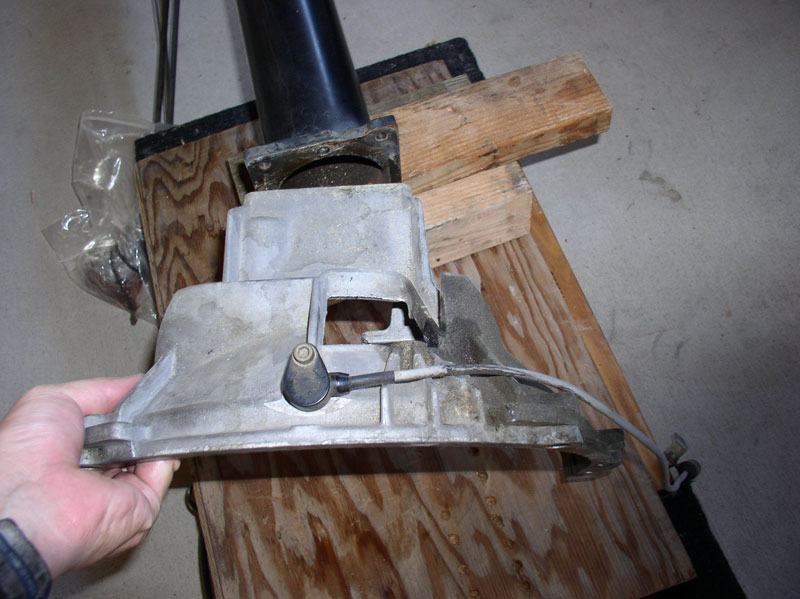
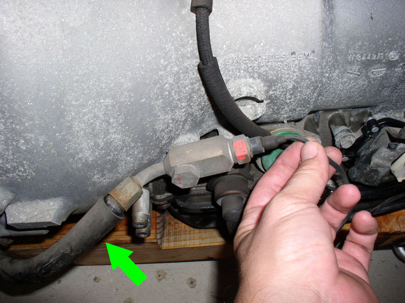
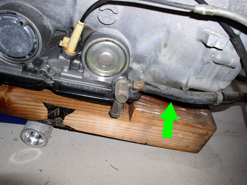
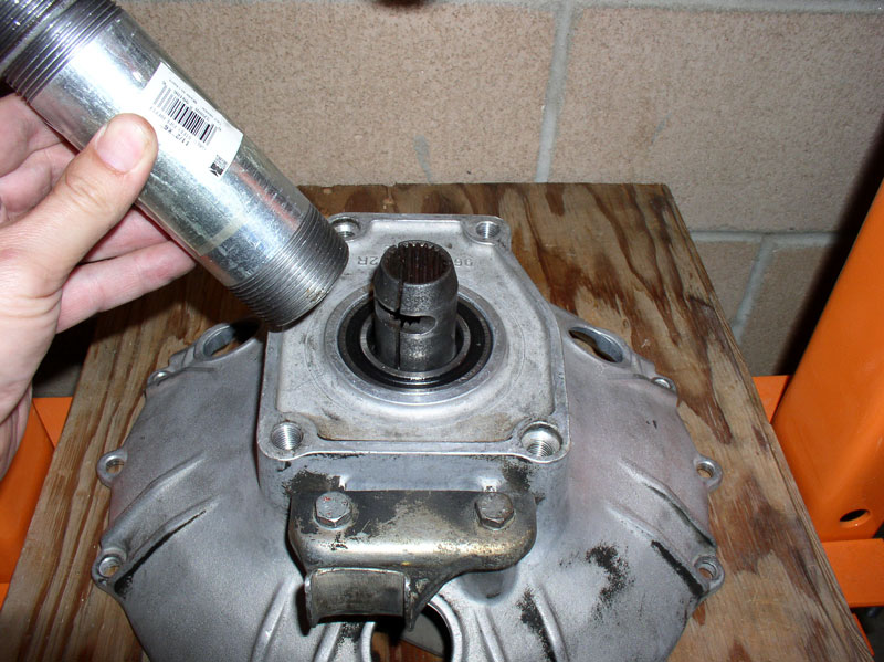
Inspect the transmission cooler lines and replace or repair as needed. There is a supply line and a return line. The supply line is the one pictured below and is connected to the transmission on the driver’s side (left side) of the transmission. It has a fitting in the end where a temperature switch is mounted as shown in the picture below. The temperature switch is used to turn on the cooling fans at the front of the engine if the transmission fluid is too warm (THANKS for the clarification, Greg Nettles). The part number for this line is 928.307.070.00 but I understand it is no longer available. However, the crimp hardware may be removed and the rubber hoses at both ends of this line may be replaced with transmission fluid resistant hose. I have not tried to replace the hose on these lines yet so don’t have pictures of the process. You will notice both lines have a protective sleeve around the rubber hose (see green arrow in picture below). Although the protective sleeves on these lines were cracked, the hose underneath was dry and flexible with no visible signs of leakage.
The return line for the transmission fluid is located on the passenger (right side) of the transmission as pictured below. This line is still available and the part number is 928.307.039.00. I have purchased a replacement line for the return but have not tried replacing the rubber hoses – although it is possible. There are 5 sealing rings for the hoses. Three sealing rings used on the passenger side (two on the banjo bolt and one on the drain port) as can be seen below. The driver’s side of the transmission takes two sealing rings for the banjo bolt. All five of the sealing rings are 14mm X 18mm in size and the part number is 900.123.007.30.
In the next chapter, I remove the bearings from the TT.
Next, remove the bolts that were temporarily installed to secure the bell housing to the TT and remove the bell housing.
Loosen the four 19mm bolts that secure the TT to the TC housing as shown. Do not remove the bolts yet.
I supported the transmission and end of the TT so weight is evenly distributed along the TT and not causing the connection at the TC housing to bind.
I then removed the 4 previously loosened bolts.
Once the bolts are removed, the TT will most likely remain attached to the TC housing due to the locating pins still being engaged. I then pulled on the TT with an up and down motion to break the TT free. If it’s being stubborn, you can use a thin flat bladed screwdriver to gently pry the TT away from the TC housing.
Once the TT is removed from the transmission, I tested the vacuum line to verify there were no leaks. If the line will not hold vacuum, check the connections and rubber hoses for leaks and replace, if needed. If the vacuum modulator on the transmission is not holding vacuum, it will need to be repaired. In my case, everything was sealed up and held vacuum with no drop after several minutes.
Inspect the transmission cooler lines and replace or repair as needed. There is a supply line and a return line. The supply line is the one pictured below and is connected to the transmission on the driver’s side (left side) of the transmission. It has a fitting in the end where a temperature switch is mounted as shown in the picture below. The temperature switch is used to turn on the cooling fans at the front of the engine if the transmission fluid is too warm (THANKS for the clarification, Greg Nettles). The part number for this line is 928.307.070.00 but I understand it is no longer available. However, the crimp hardware may be removed and the rubber hoses at both ends of this line may be replaced with transmission fluid resistant hose. I have not tried to replace the hose on these lines yet so don’t have pictures of the process. You will notice both lines have a protective sleeve around the rubber hose (see green arrow in picture below). Although the protective sleeves on these lines were cracked, the hose underneath was dry and flexible with no visible signs of leakage.
The return line for the transmission fluid is located on the passenger (right side) of the transmission as pictured below. This line is still available and the part number is 928.307.039.00. I have purchased a replacement line for the return but have not tried replacing the rubber hoses – although it is possible. There are 5 sealing rings for the hoses. Three sealing rings used on the passenger side (two on the banjo bolt and one on the drain port) as can be seen below. The driver’s side of the transmission takes two sealing rings for the banjo bolt. All five of the sealing rings are 14mm X 18mm in size and the part number is 900.123.007.30.
In the next chapter, I remove the bearings from the TT.
Last edited by Dwayne; 12-19-2010 at 08:15 PM.
 12-19-2010, 07:12 PM
#32
Rennlist Member
Thread Starter
Join Date: Sep 2007
Location: Ridgecrest, California
Posts: 1,363
Likes: 0
Received 143 Likes
on
28 Posts
CH07 REMOVING TT BEARINGS
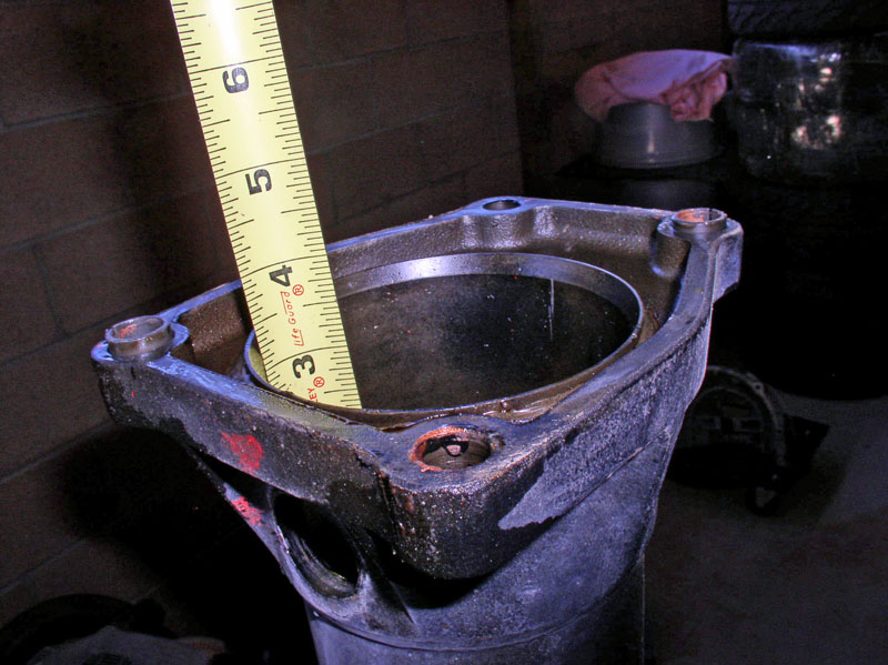
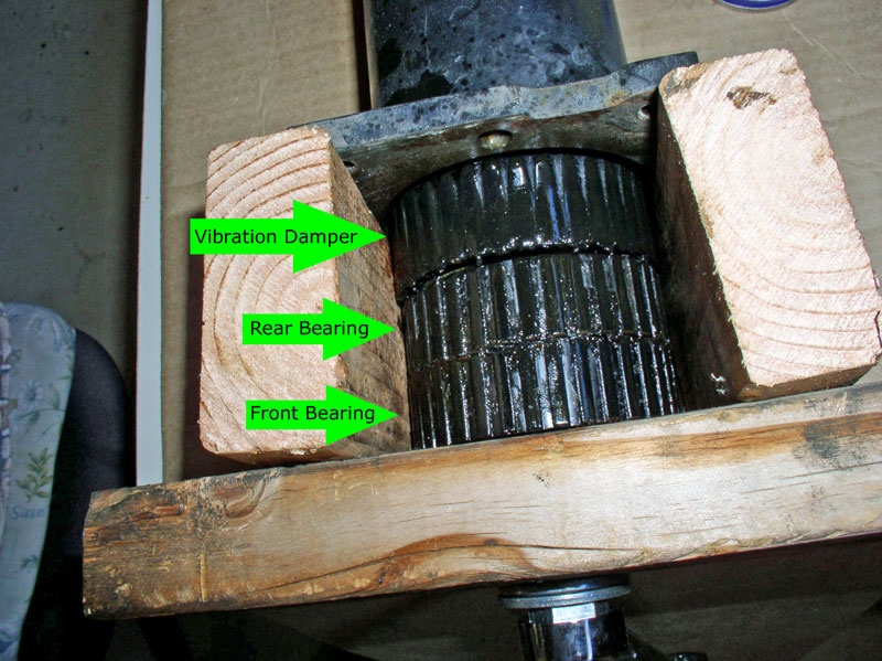
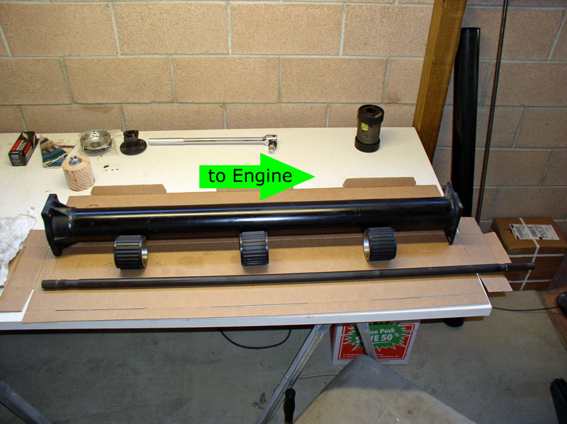
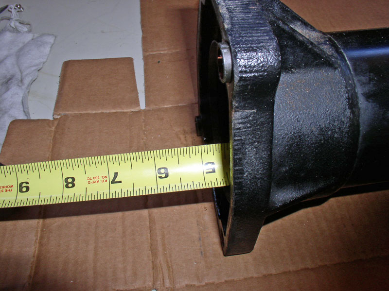
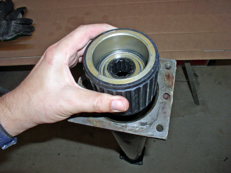
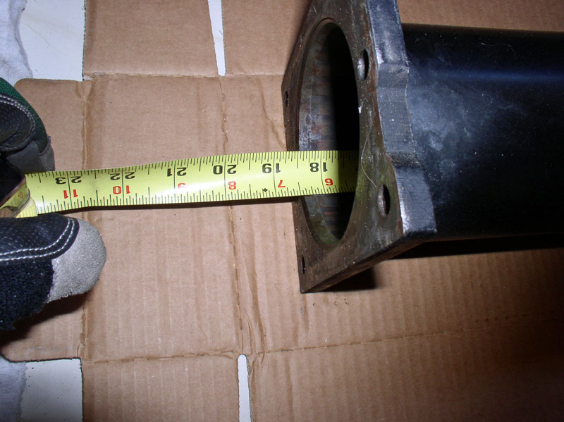
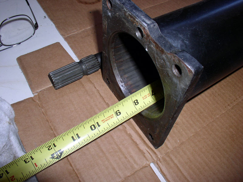
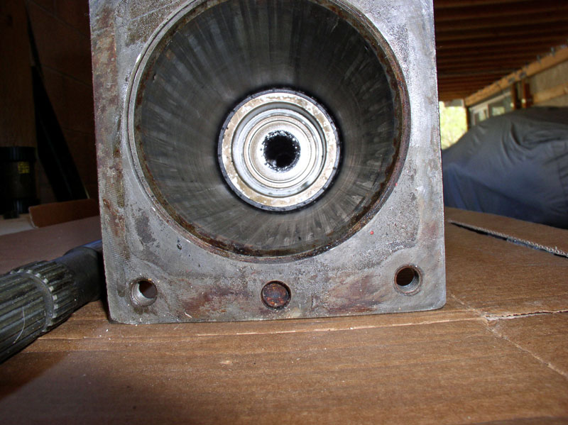
Looking into the rear of the TT, you can see the vibration damper. The damper does not touch the drive shaft.
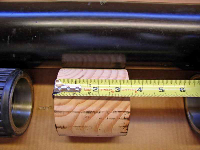
For reference, I measured the distance of vibration damper to the end of the TT. In this case, mine was about 3 � inches.
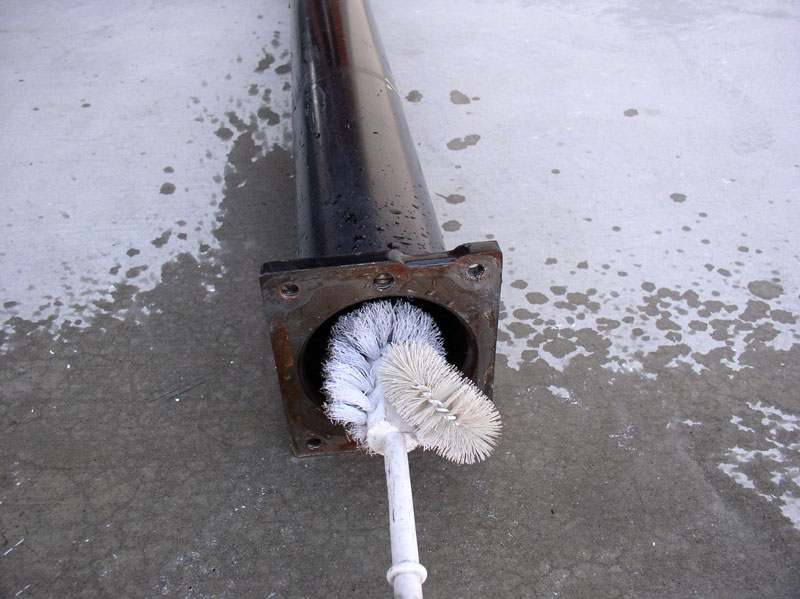
I planned to pull the bearings out the front end of the TT using a threaded rod. But I believe one could pull the bearings out the rear end of the TT as well. I noticed that the inside of the TT was dirty with stuck on debris and thought it would be best to clean this debris out before dragging the bearing carriers over it.
I used orange citrus degreaser/cleaner on the inside of the TT. Some time ago, I purchased a toilet bowl cleaner for jobs such as this and it worked great for this application.
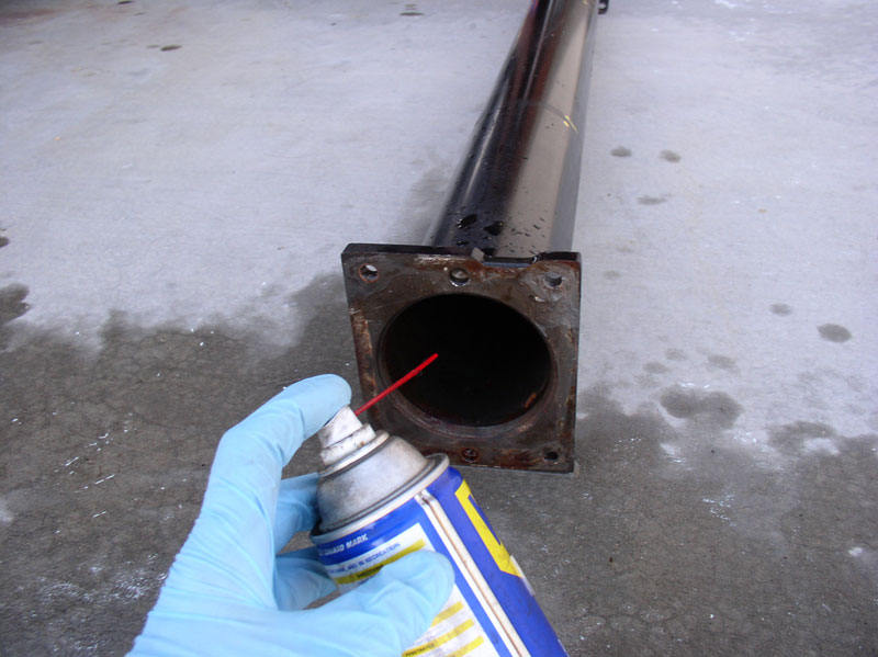
After rinsing and drying the inside of the TT, I sprayed WD-40 on the inside of the TT to help ease the removal of the bearing carriers.
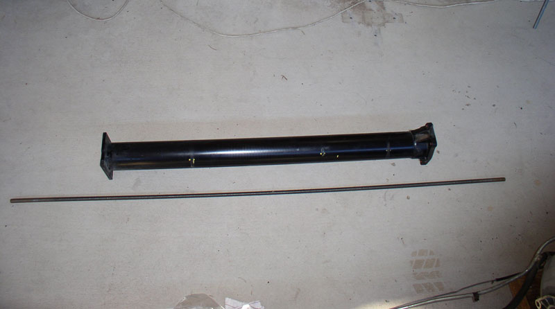
I used a 6 foot 5/8 inch threaded rod with thread pitch 11 (i.e., 11 threads per inch). Keep in mind it will take more revolutions and take longer if a fine thread is used (i.e., more threads per inch). Given the length of the TT, I could have cut the threaded rod down to about 5 feet but having the extra length didn�t cause any problems. I found the threaded rod on ebay that is sold by Moin Hardware Inc. for $18.95. Here�s the link: http://cgi.ebay.com/ws/eBayISAPI.dll...m=310186293661 . You will also need 4 nuts and 4 washers to use with the threaded rod extraction method. I picked these nuts and washers up from the local Home Depot store.
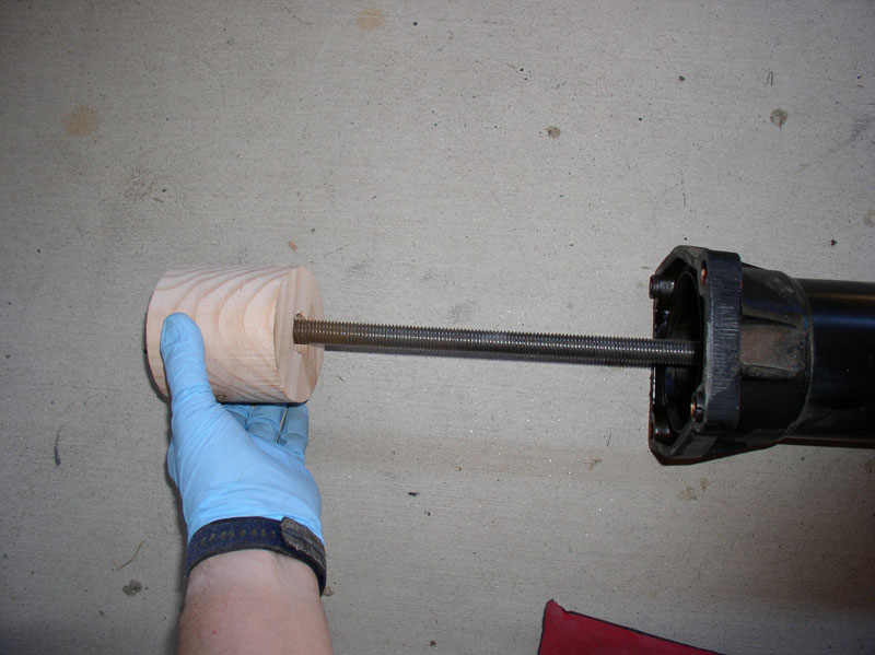
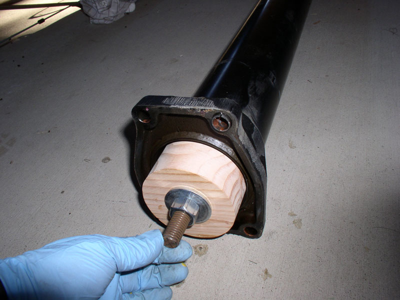
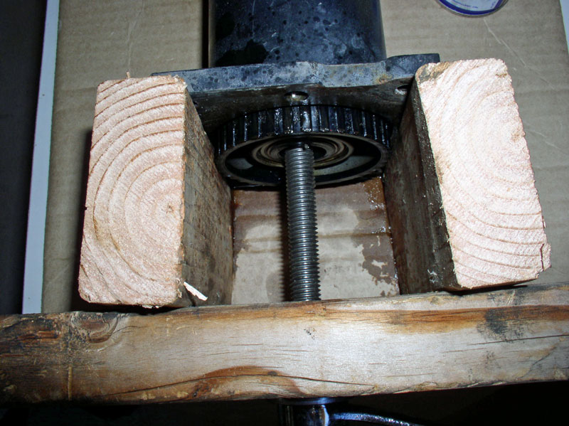
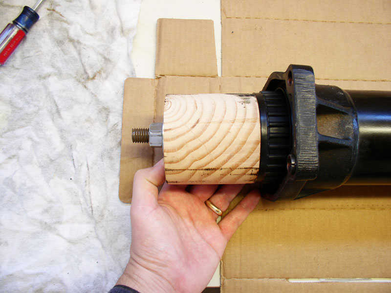
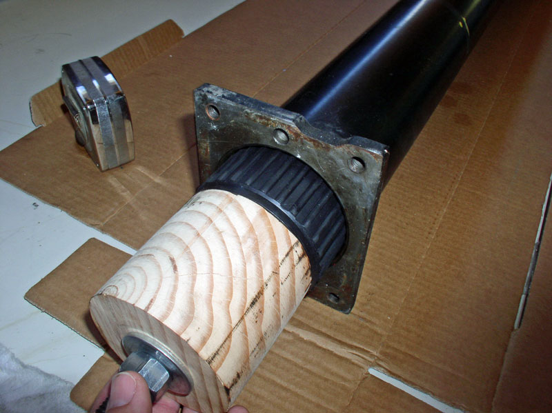
I inserted the threaded rod into the TT through the centers of the bearing carriers. I fabricated a wooden shuttle that looks a little like a roll of toilet paper. A detailed description of this custom tool is included in CH01 PARTS-TOOLS-PREPARATION under the �Custom Tools� section. Since I�d be pulling the bearings and vibration damper out the front of the TT, I installed the shuttle on the threaded rod at the rear of the TT as pictured below.
Install one washer and one nut on the end of the threaded rod as shown in the picture below.
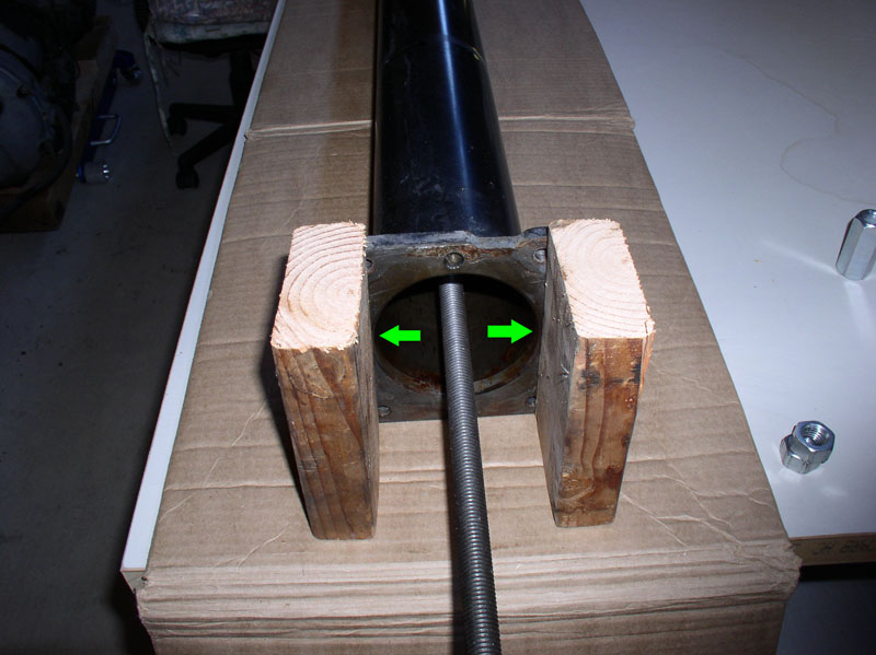
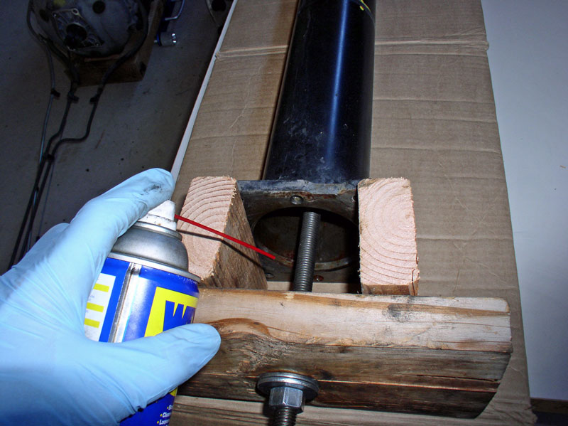
At the front of the TT, I used two scraps of 2 X 4 lumber about 6 inches in length and positioned them in front of the TT as pictured below. This is to provide clearance for the bearings to fully exit the TT without interference. Ensure the 2 X 4s are not blocking the opening of the TT.
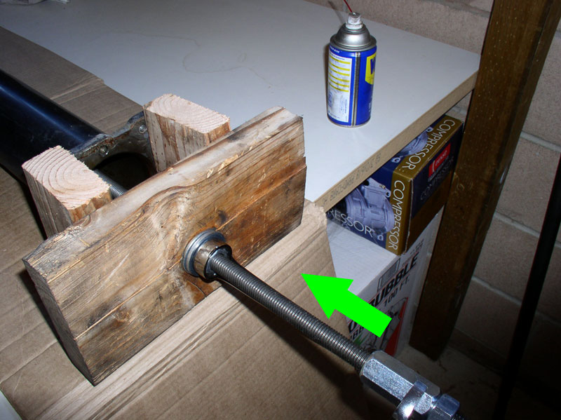
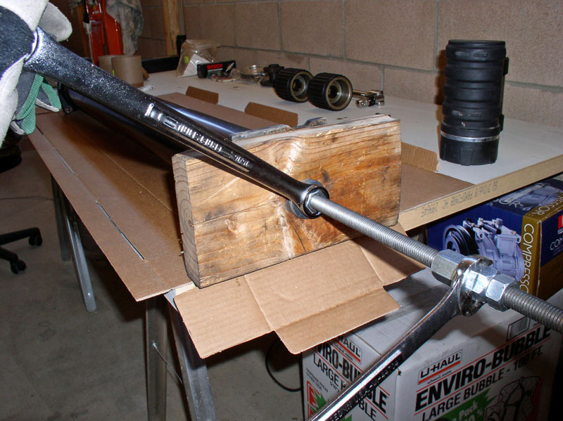
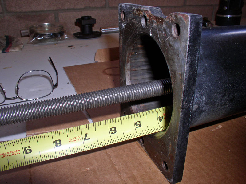
I used a scrap of 2 X 6 lumber about 12 inches in length to provide the counter force for the pulling action. I drilled a 1� hole through the center and installed it on the threaded rod as pictured below.
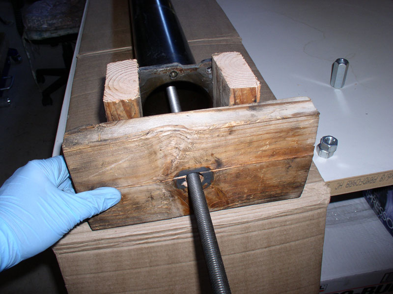
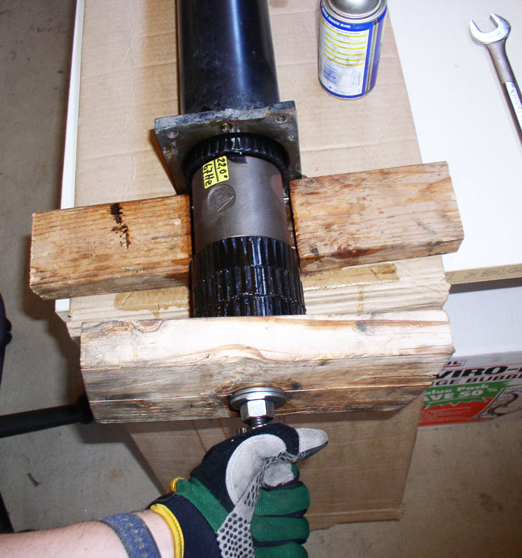
Next, I installed 2 washers and a nut against the 2 X 6. I threaded 2 additional nuts an inch or two away. The two nuts at the end are used to lock firmly against each other and will prevent the threaded rod from turning when turning the nut against the 2 X 6. Don�t lock these last two nuts together just yet until you get the wrench on.
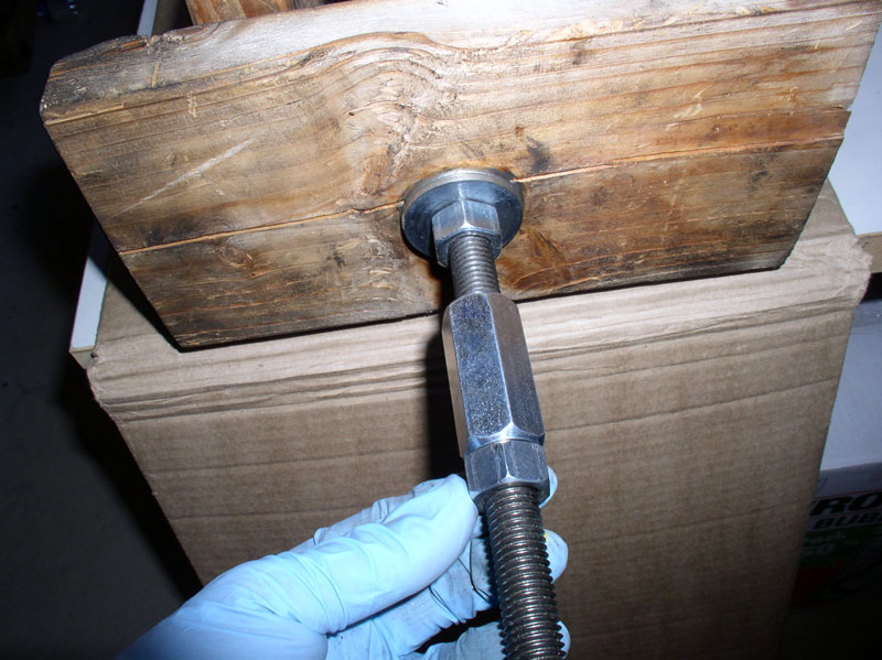
Slide a long handled closed end wrench over the nuts. Use another wrench to counter hold the rod in place using the locking nuts as shown below. The wrenches I used here are 15/16 inch.
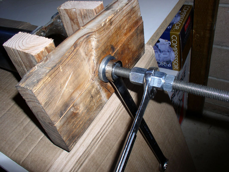
To increase the ease of removal, I sprayed WD-40 on the threads of the rod and a small amount on the two washers between the nut and 2 X 6.
As you begin tightening (turning clockwise) the nut next to the 2 X 6, you will notice the shuttle starting to move forward pulling everything in its path along with it.
A found this process to work quite easy with little effort. As you continue to �pull� the rod through the TT, the distance between the locking nuts and the torquing nut increases quite a bit. If it�s easier, you can relocate the locking nuts to be closer to the torquing nut.
Continued...
Looking into the rear of the TT, you can see the vibration damper. The damper does not touch the drive shaft.
For reference, I measured the distance of vibration damper to the end of the TT. In this case, mine was about 3 � inches.
I planned to pull the bearings out the front end of the TT using a threaded rod. But I believe one could pull the bearings out the rear end of the TT as well. I noticed that the inside of the TT was dirty with stuck on debris and thought it would be best to clean this debris out before dragging the bearing carriers over it.
I used orange citrus degreaser/cleaner on the inside of the TT. Some time ago, I purchased a toilet bowl cleaner for jobs such as this and it worked great for this application.
After rinsing and drying the inside of the TT, I sprayed WD-40 on the inside of the TT to help ease the removal of the bearing carriers.
I used a 6 foot 5/8 inch threaded rod with thread pitch 11 (i.e., 11 threads per inch). Keep in mind it will take more revolutions and take longer if a fine thread is used (i.e., more threads per inch). Given the length of the TT, I could have cut the threaded rod down to about 5 feet but having the extra length didn�t cause any problems. I found the threaded rod on ebay that is sold by Moin Hardware Inc. for $18.95. Here�s the link: http://cgi.ebay.com/ws/eBayISAPI.dll...m=310186293661 . You will also need 4 nuts and 4 washers to use with the threaded rod extraction method. I picked these nuts and washers up from the local Home Depot store.
I inserted the threaded rod into the TT through the centers of the bearing carriers. I fabricated a wooden shuttle that looks a little like a roll of toilet paper. A detailed description of this custom tool is included in CH01 PARTS-TOOLS-PREPARATION under the �Custom Tools� section. Since I�d be pulling the bearings and vibration damper out the front of the TT, I installed the shuttle on the threaded rod at the rear of the TT as pictured below.
Install one washer and one nut on the end of the threaded rod as shown in the picture below.
At the front of the TT, I used two scraps of 2 X 4 lumber about 6 inches in length and positioned them in front of the TT as pictured below. This is to provide clearance for the bearings to fully exit the TT without interference. Ensure the 2 X 4s are not blocking the opening of the TT.
I used a scrap of 2 X 6 lumber about 12 inches in length to provide the counter force for the pulling action. I drilled a 1� hole through the center and installed it on the threaded rod as pictured below.
Next, I installed 2 washers and a nut against the 2 X 6. I threaded 2 additional nuts an inch or two away. The two nuts at the end are used to lock firmly against each other and will prevent the threaded rod from turning when turning the nut against the 2 X 6. Don�t lock these last two nuts together just yet until you get the wrench on.
Slide a long handled closed end wrench over the nuts. Use another wrench to counter hold the rod in place using the locking nuts as shown below. The wrenches I used here are 15/16 inch.
To increase the ease of removal, I sprayed WD-40 on the threads of the rod and a small amount on the two washers between the nut and 2 X 6.
As you begin tightening (turning clockwise) the nut next to the 2 X 6, you will notice the shuttle starting to move forward pulling everything in its path along with it.
A found this process to work quite easy with little effort. As you continue to �pull� the rod through the TT, the distance between the locking nuts and the torquing nut increases quite a bit. If it�s easier, you can relocate the locking nuts to be closer to the torquing nut.
Continued...
12-19-2010, 07:19 PM
#33
Rennlist Member
Thread Starter
Join Date: Sep 2007
Location: Ridgecrest, California
Posts: 1,363
Likes: 0
Received 143 Likes
on
28 Posts
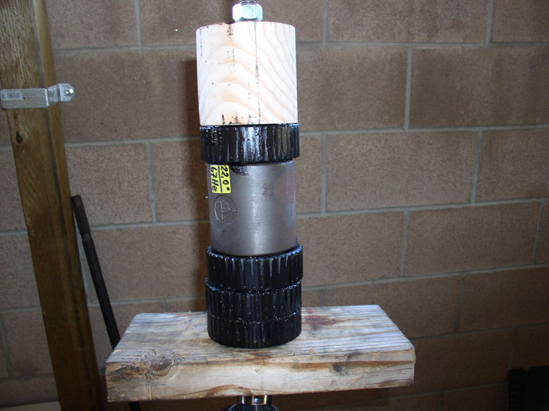
Soon, you will begin to see the first bearing carrier emerge from the TT. The other bearing carrier and vibration damper will be right behind it. Continue turning the nut….
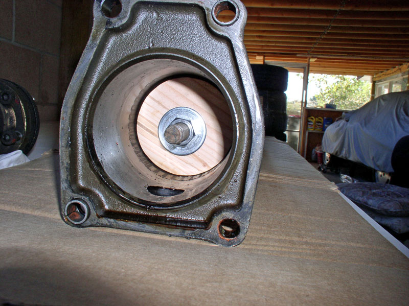
….until you have reached the 2 X 6 as shown below.
At this point, I was able to hold the TT in place with one hand and pull on the threaded rod with the other and remove the assembly.
You will end up with something looking like a bearing sis kabob. Now you can remove the nut on the end of the rod and remove the wooden shuttle and bearings.
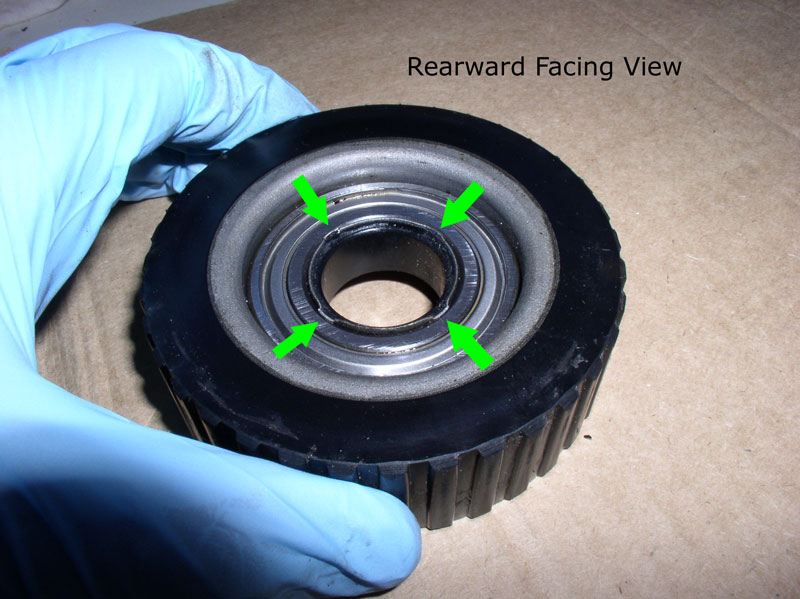
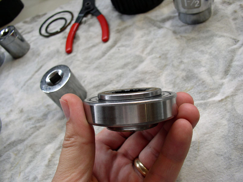
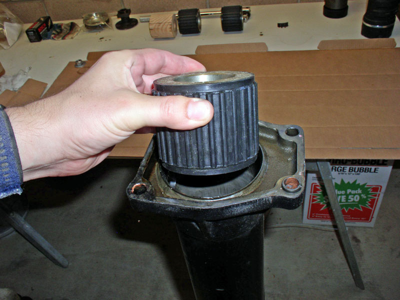
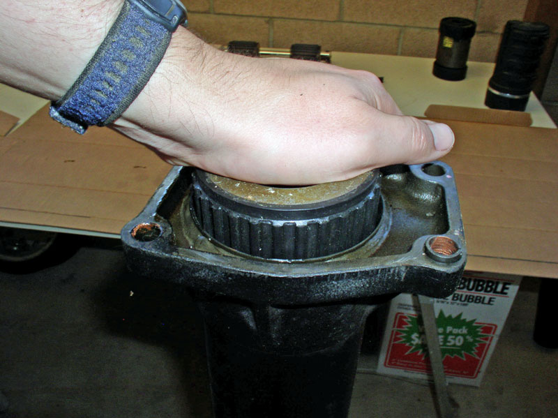
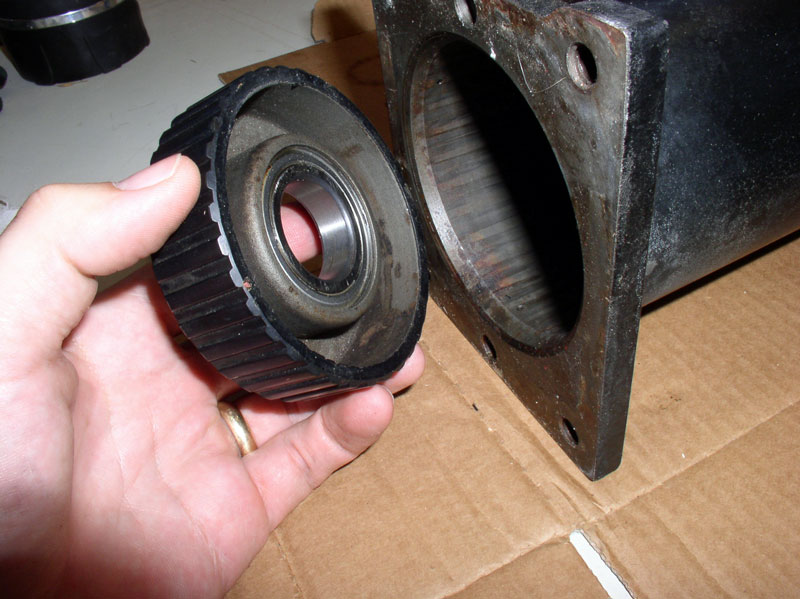
After cleaning the bearing carriers, I took a closer inspection. The bearings themselves are pressed into a rubberized metal carrier. In addition, there is a thin metal insert also with a thin rubber-like coating pressed into the center of the bearing. You can see from the picture below there are 4 locking tabs pressed outward on the center insert to help secure the insert to the bearing. The rearward facing view is the side that is facing the rear of the car (facing the transmission).
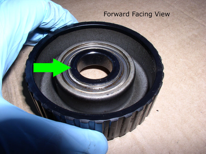
Looking at the forward facing view (facing the front of the car), you can see the flange on the rubber coated center insert mounted flush against the bearing. The bearing itself is pressed flush against the lip on the carrier as well.
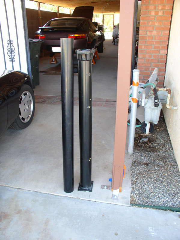
Next, I prepared the TT for the new bearings. I needed to clean away the excess WD-40 so the new bearing carriers would stay put when installed. I used standard black 3 � inch plastic pipe available at Home Depot for the job. I bought a 10 foot section and cut a piece that was a little longer than the TT as shown.
I sprayed generous amounts of citrus degreaser cleaner inside the TT and let it run down to the opposite end.
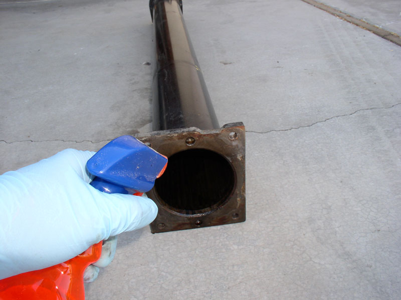
Place a thin cloth towel or a thick paper towel around the end of the plastic pipe and push it through to the end of the TT until the towel comes out the end. I found it helpful to also twist the plastic pipe while pushing and it helped clean the inside of the TT better. I repeated this procedure of spraying the inside with cleaner then following with a towel until the towel came out the other end with little or no dirt on it. It took three applications for my TT.
Removing and replacing the Torque Converter bearings is covered in the next chapter.
….until you have reached the 2 X 6 as shown below.
At this point, I was able to hold the TT in place with one hand and pull on the threaded rod with the other and remove the assembly.
You will end up with something looking like a bearing sis kabob. Now you can remove the nut on the end of the rod and remove the wooden shuttle and bearings.
After cleaning the bearing carriers, I took a closer inspection. The bearings themselves are pressed into a rubberized metal carrier. In addition, there is a thin metal insert also with a thin rubber-like coating pressed into the center of the bearing. You can see from the picture below there are 4 locking tabs pressed outward on the center insert to help secure the insert to the bearing. The rearward facing view is the side that is facing the rear of the car (facing the transmission).
Looking at the forward facing view (facing the front of the car), you can see the flange on the rubber coated center insert mounted flush against the bearing. The bearing itself is pressed flush against the lip on the carrier as well.
Next, I prepared the TT for the new bearings. I needed to clean away the excess WD-40 so the new bearing carriers would stay put when installed. I used standard black 3 � inch plastic pipe available at Home Depot for the job. I bought a 10 foot section and cut a piece that was a little longer than the TT as shown.
I sprayed generous amounts of citrus degreaser cleaner inside the TT and let it run down to the opposite end.
Place a thin cloth towel or a thick paper towel around the end of the plastic pipe and push it through to the end of the TT until the towel comes out the end. I found it helpful to also twist the plastic pipe while pushing and it helped clean the inside of the TT better. I repeated this procedure of spraying the inside with cleaner then following with a towel until the towel came out the other end with little or no dirt on it. It took three applications for my TT.
Removing and replacing the Torque Converter bearings is covered in the next chapter.
12-19-2010, 07:53 PM
#34
Rennlist Member
Thread Starter
Join Date: Sep 2007
Location: Ridgecrest, California
Posts: 1,363
Likes: 0
Received 143 Likes
on
28 Posts
CH08 REMOVING AND INSTALLING TC BEARINGS
At this point, I have to change gears on this write up because I did not change the Torque Converter (TC) bearings on the �87. However, I did change the TC bearings on the �84 during this timeframe and did take pictures of that procedure. So, I offer the �84 automatic transmission TC bearings replacement as an alternative. Unfortunately, since I have not changed the TC bearings on an �87, I can�t comment on any known differences but am hopeful the procedure is very similar. All the other chapters in the overall write up are for an �87.
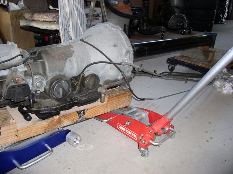
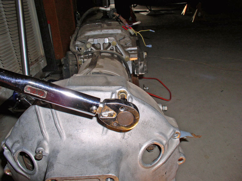
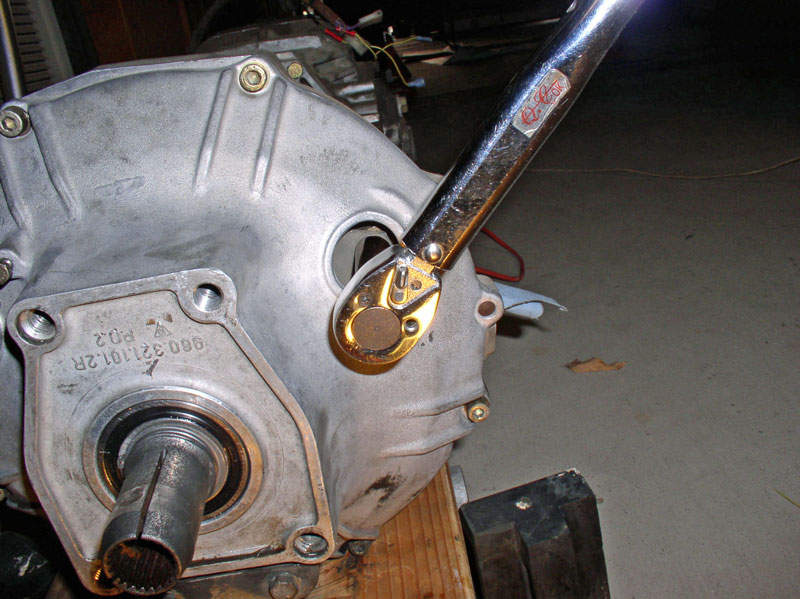
First, I made sure the transmission and TC were on a stable platform suitable to remain upright while taking the TC housing cover off and removing the flex plate bolts. I left the transmission on the wooden platform I fabricated and lowered the floor jack all the way down to the ground and it worked great for keeping the transmission stable. There are two sets of bolts to be removed in order to separate the TC housing from the transmission. They are the 6mm Allen Head bolts that secure the TC housing to the transmission housing and the six 13mm bolts visible through the inspection holes of the TC housing that secure the flex plate to the Torque Converter. I removed the 8 TC housing bolts using a 6mm Allen Head socket first but in hindsight, I would probably remove the 13mm bolts on the flex plate first since the TC housing is used to lever against when removing the 13mm bolts so it�s a good idea for the TC housing to remain secured when removing the 13mm bolts.
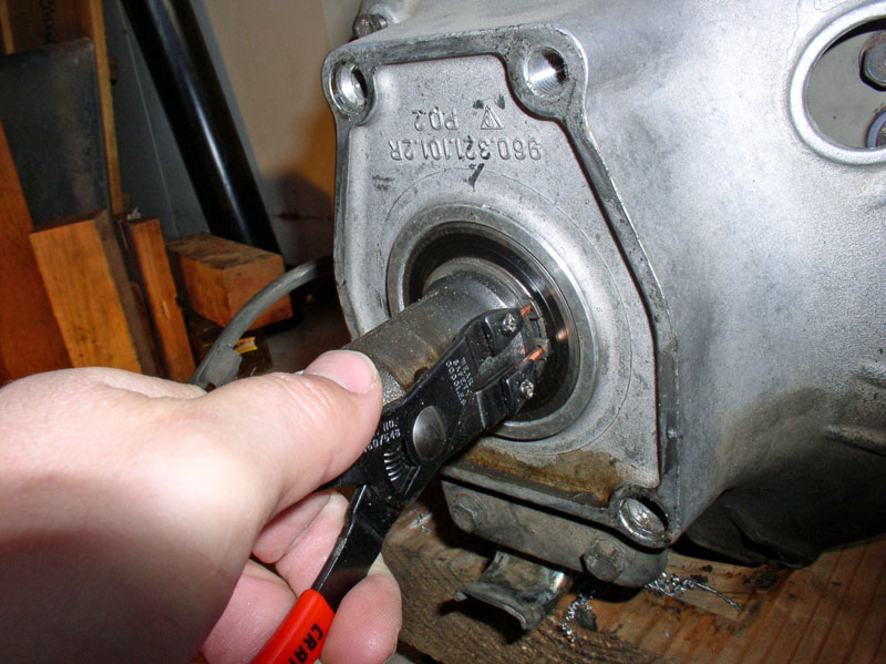
I removed the snap ring on the front of the TC housing. It is not required to remove this clip in order to remove the TC housing from the transmission as it does not attach the drive plate to the transmission. However, it will need to be removed eventually in order to press out the drive plate from the TC housing once the housing is removed.
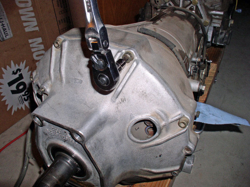
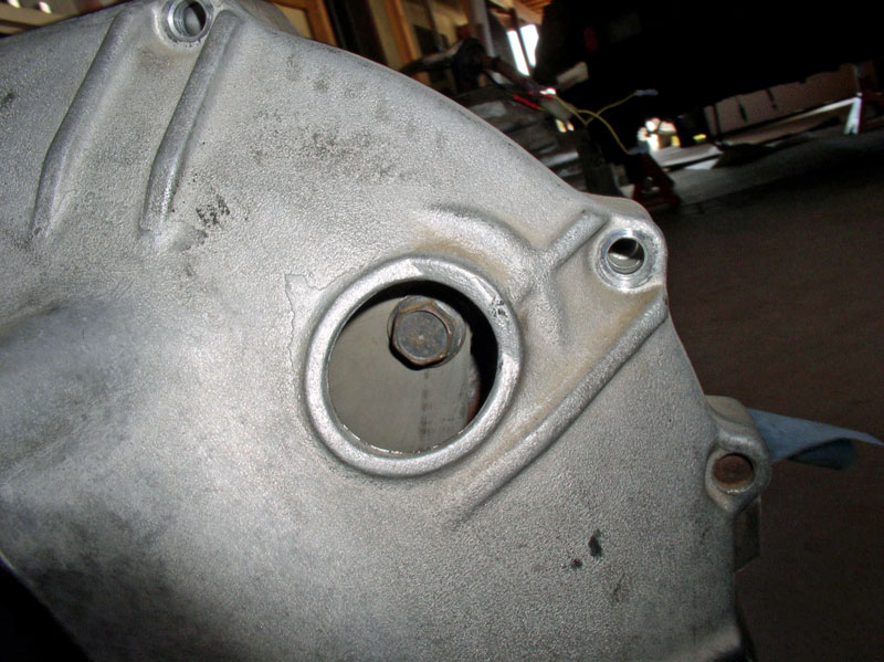
I rotated the drive plate in a clockwise manner until one of the 13mm flex plate bolts was visible through the inspection hole. You will notice that when one bolt is lined up on an inspection hole, the other bolts are also lined up with the other inspection holes.
Remove the 13mm bolt. I did not find it necessary to clamp the transmission in place to prevent it from spinning while loosening the bolts since the TC housing inspection hole provided the counter force needed to loosen the bolts.
Next, I carefully pried the TC housing away from the transmission housing using a thin flat blade screwdriver.
I pulled the housing away from the transmission�.
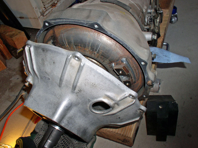
�.and marked the flex plate�..
�.and TC so I could orient the flex plate to the exact same mounting as originally configured.
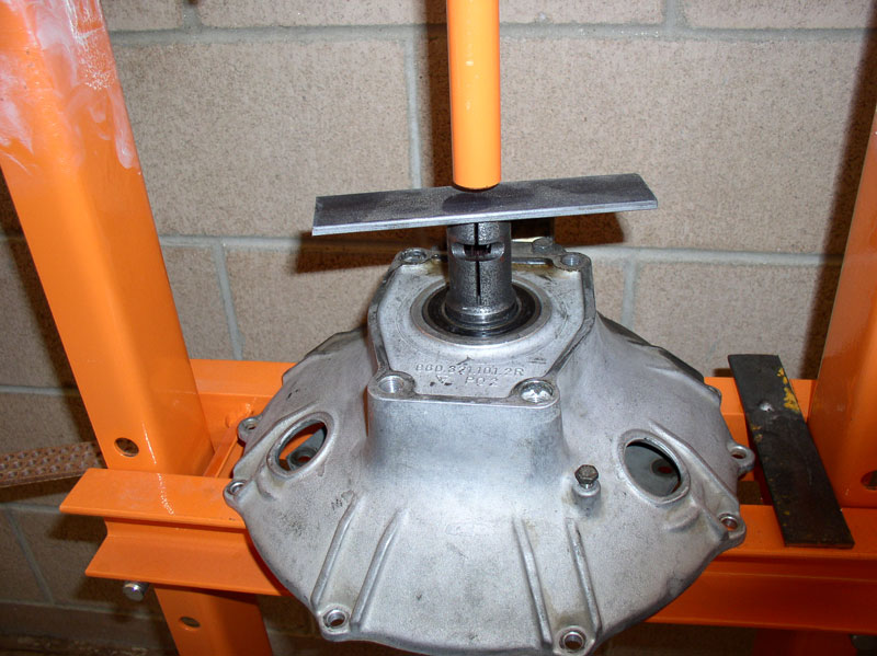
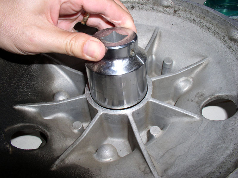
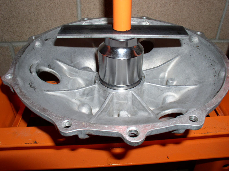
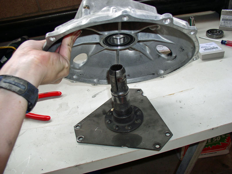
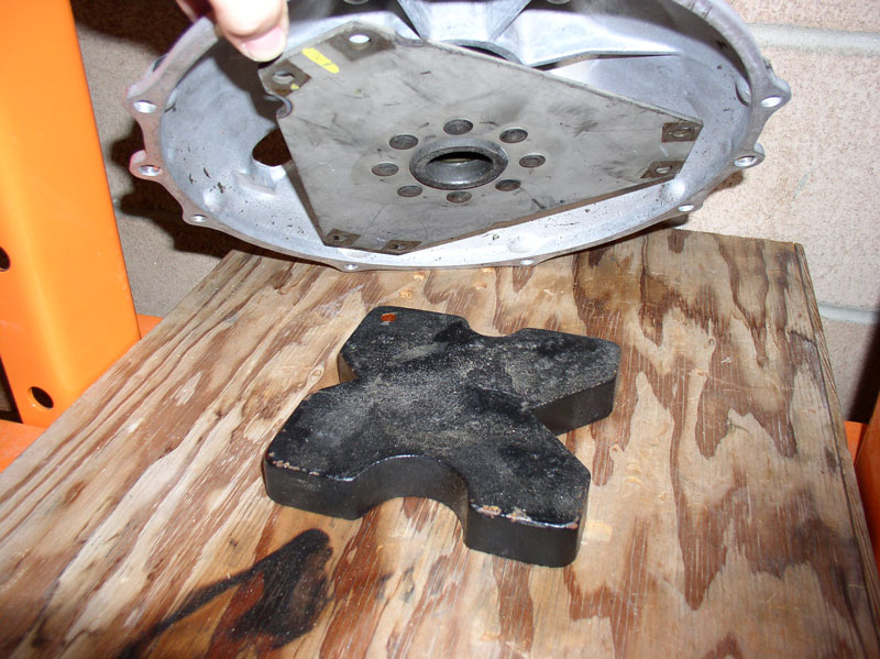
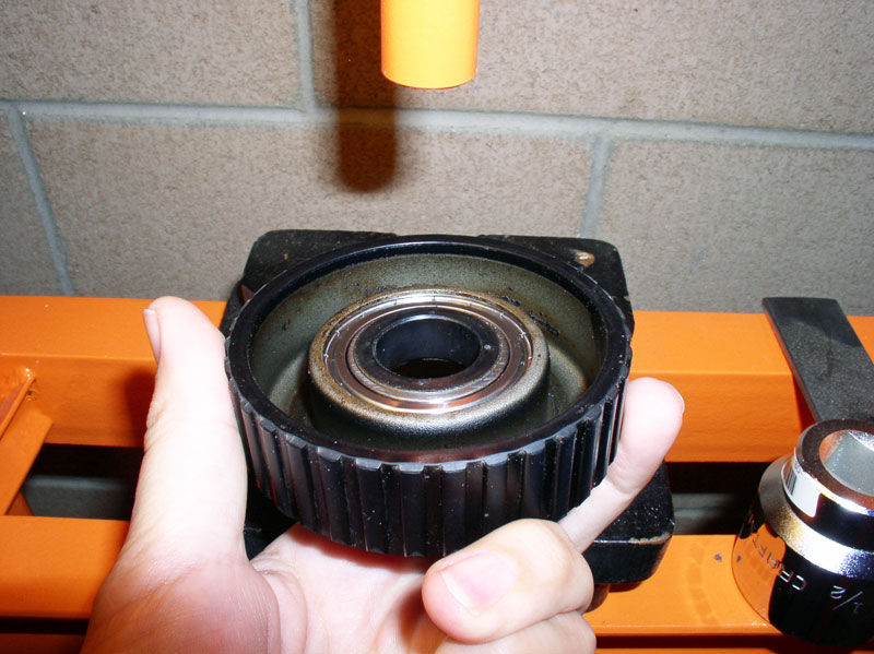
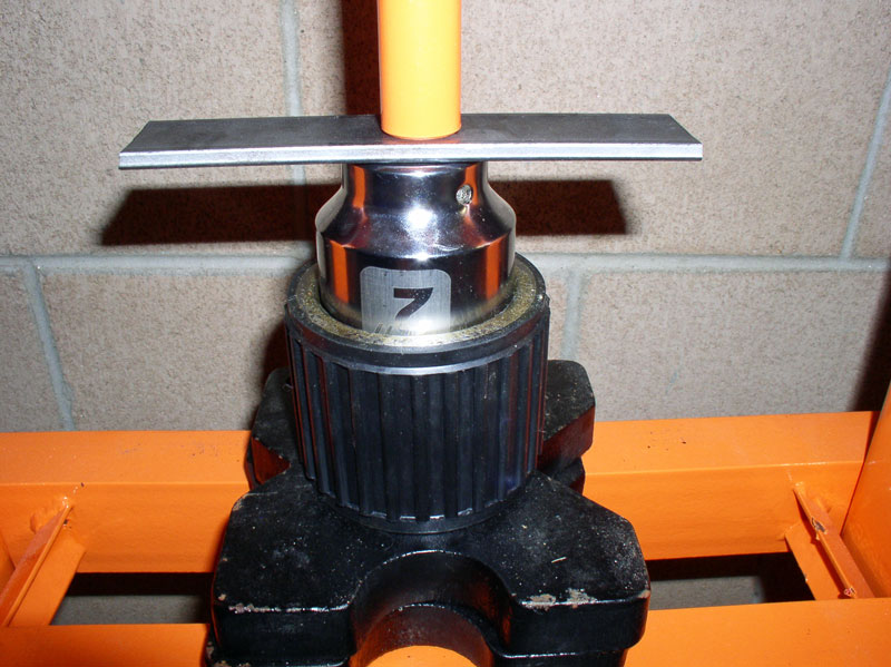
I pressed out the drive plate from the TC housing using the shop press and a piece of scrap plate steel as shown in the picture below.
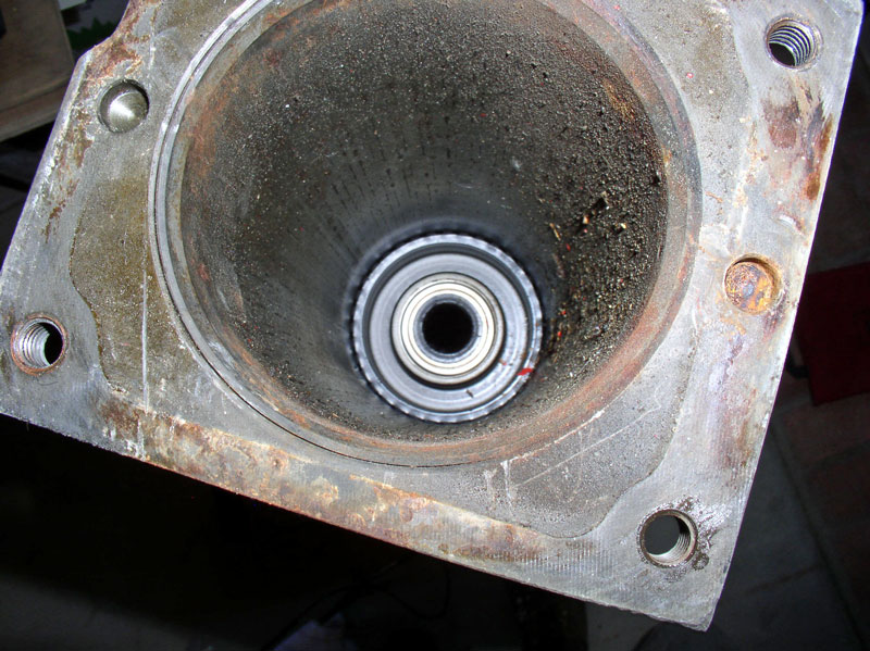
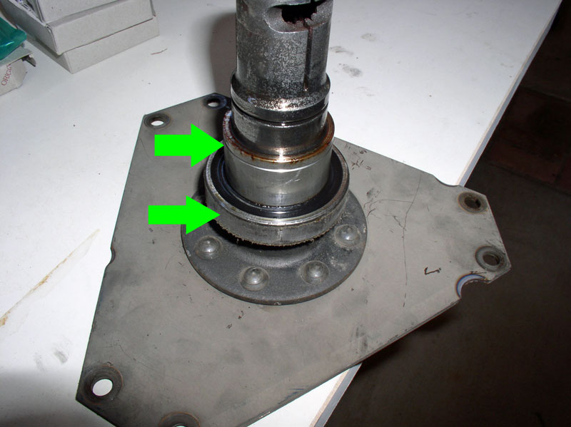
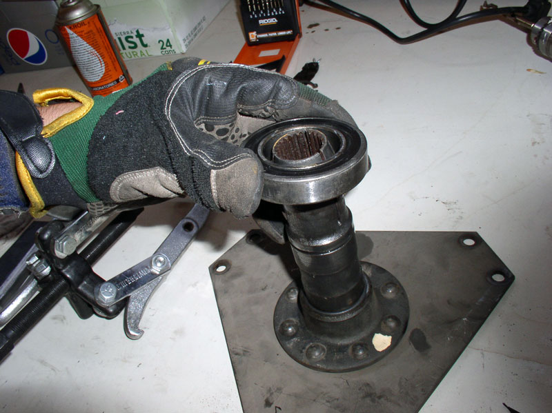
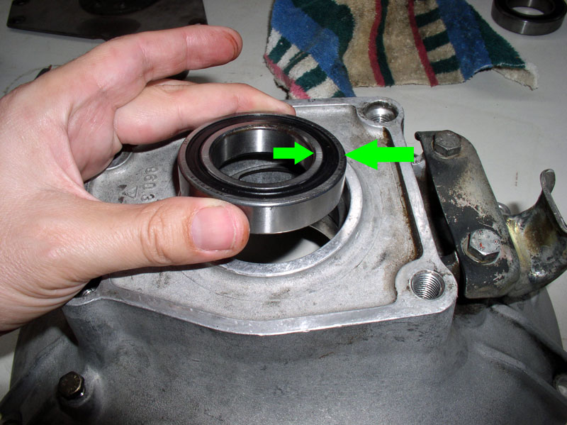
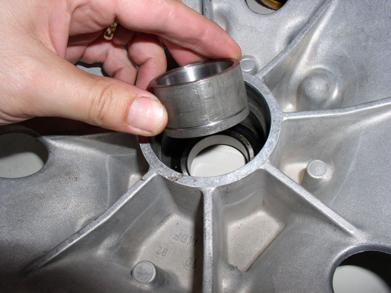
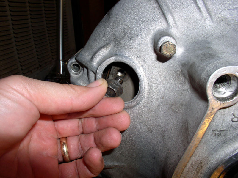
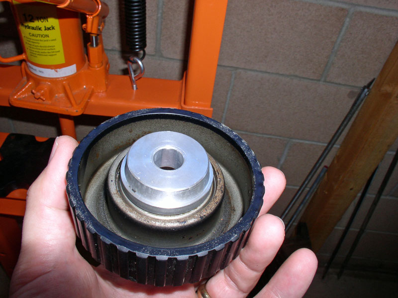
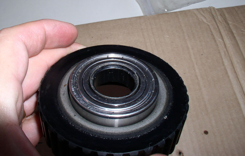
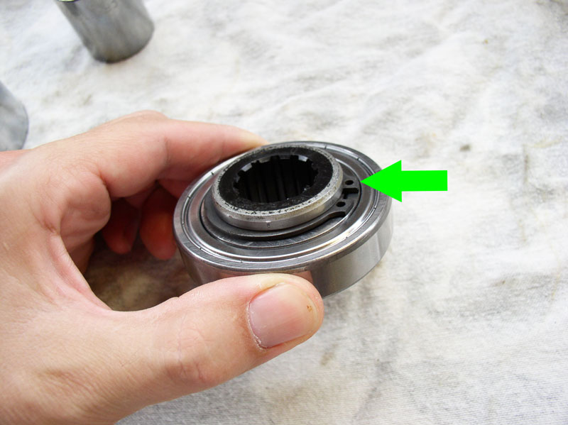
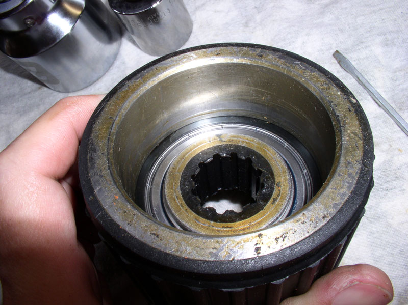
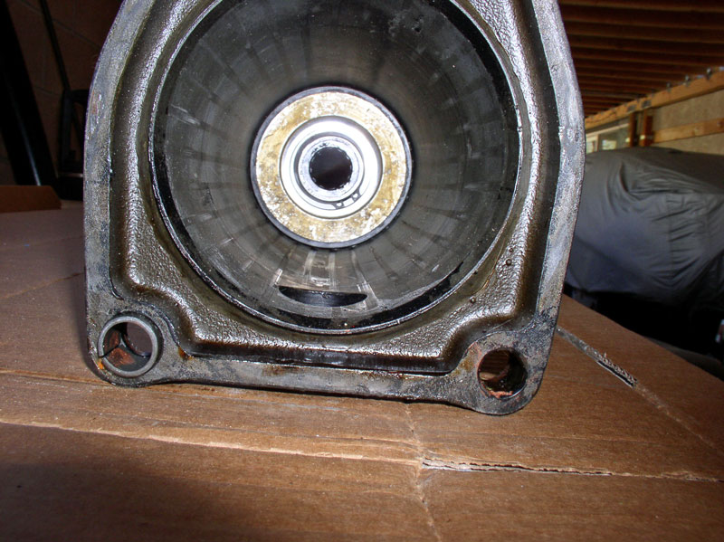
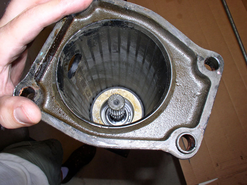
There are two bearings in the TC Housing. A forward bearing (toward the front of the car) and a rearward bearing (toward the rear of the car). Once the drive plate was removed, I noticed the rearward bearing was still attached to the drive plate (bottom arrow in the pic below). Also attached was a collar that sits between the two bearings (top arrow in the pic below).
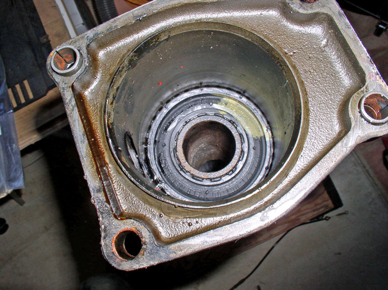
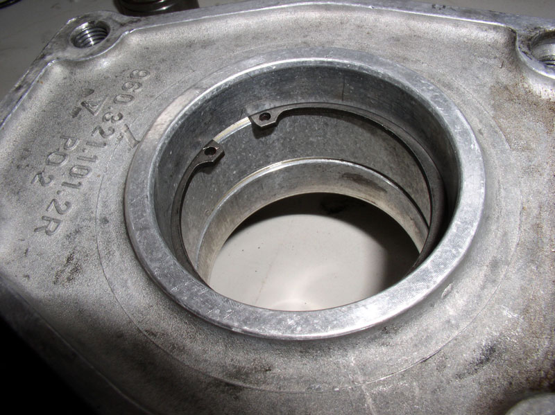
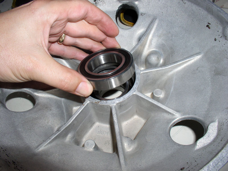
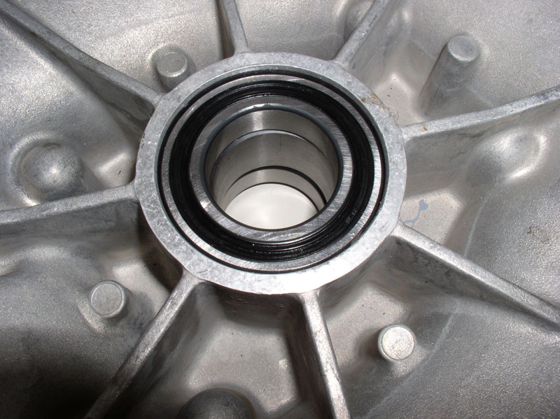
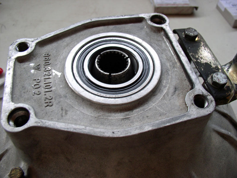
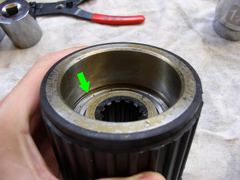
Looking at the inside of the TC housing, I could see the forward bearing and two snap rings. The snap rings appear to serve as stops for the forward and rearward bearings.
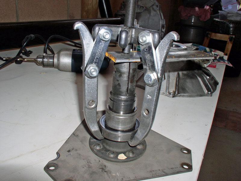
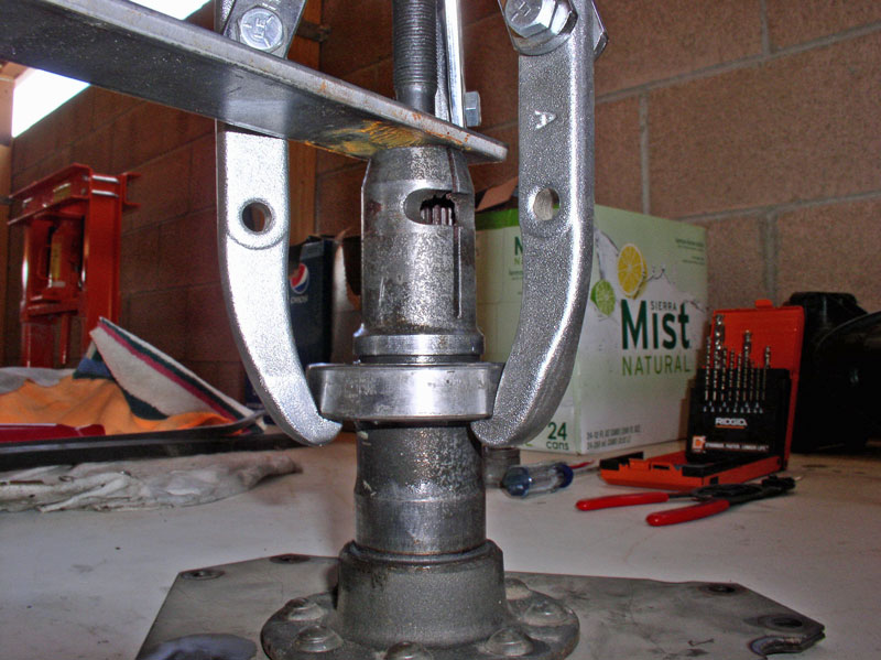
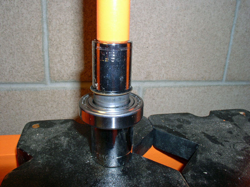
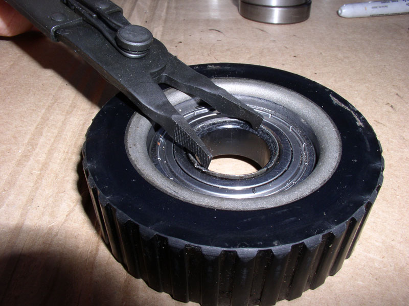
Next, I set about to remove the rearward bearing and collar from the drive plate. For this, I used a 3-Jaw pulley puller and used a piece of scrap plate steel on top of the splines to lever against as shown in the pic below. I bought the scrap plate steel from Home Depot and cut it to size with a hacksaw.
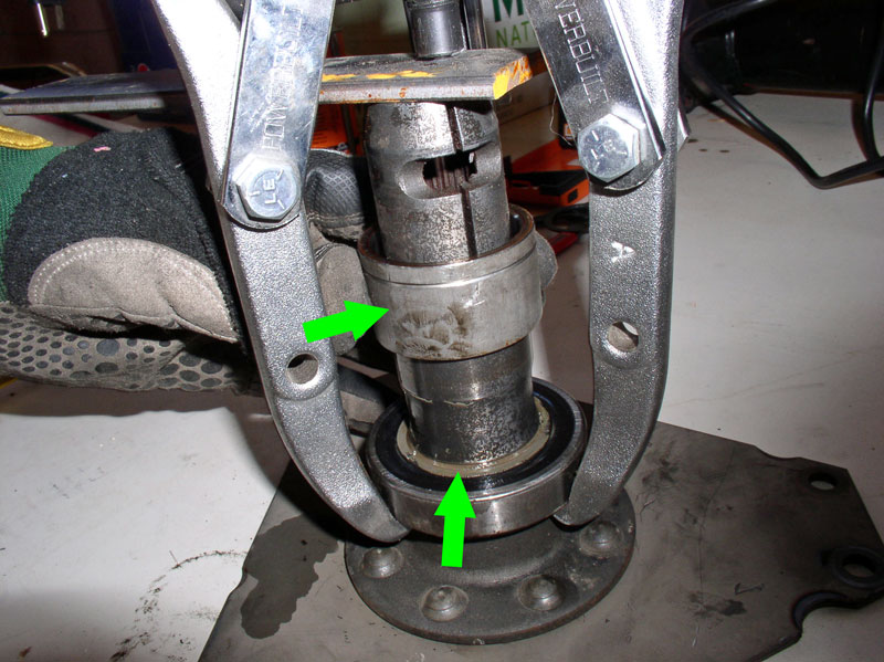
An interesting thing happened when I began to pull the bearing. The collar broke loose and I found it easily slid up and down the drive plate shaft (i.e., it is not pressed on). I also noticed what appeared to be a sealant of some kind at the base of the collar and the bearing (see bottom arrow in the pic).
So, I remove the 3-Jaw puller and removed the collar. In hindsight, I probably could have removed the collar before installing the 3-Jaw puller in the first place.
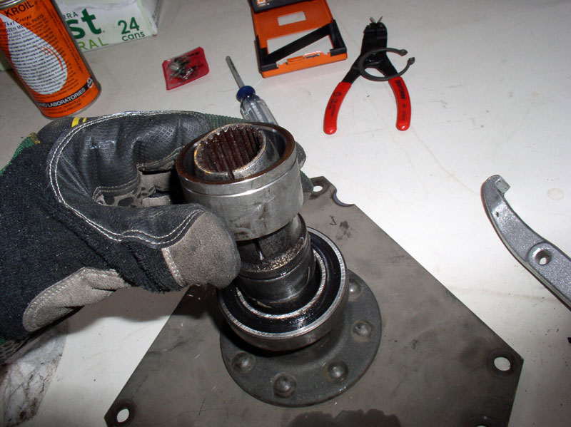
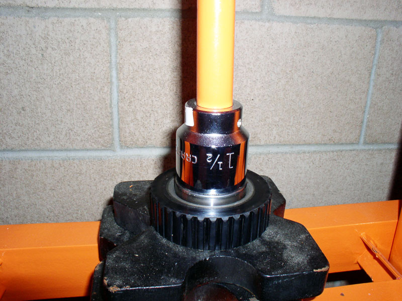
I re-installed the 3-Jaw puller and continued pulling the bearing off the drive plate shaft. With the collar removed, you will notice the diameter of the drive plate shaft is thicker in two areas on the shaft. These two areas are where the forward and rearward bearings are pressed on to the shaft. The 3-Jaw puller was needed to pull the bearing over both of these thicker areas on the shaft.
Continued....
At this point, I have to change gears on this write up because I did not change the Torque Converter (TC) bearings on the �87. However, I did change the TC bearings on the �84 during this timeframe and did take pictures of that procedure. So, I offer the �84 automatic transmission TC bearings replacement as an alternative. Unfortunately, since I have not changed the TC bearings on an �87, I can�t comment on any known differences but am hopeful the procedure is very similar. All the other chapters in the overall write up are for an �87.
First, I made sure the transmission and TC were on a stable platform suitable to remain upright while taking the TC housing cover off and removing the flex plate bolts. I left the transmission on the wooden platform I fabricated and lowered the floor jack all the way down to the ground and it worked great for keeping the transmission stable. There are two sets of bolts to be removed in order to separate the TC housing from the transmission. They are the 6mm Allen Head bolts that secure the TC housing to the transmission housing and the six 13mm bolts visible through the inspection holes of the TC housing that secure the flex plate to the Torque Converter. I removed the 8 TC housing bolts using a 6mm Allen Head socket first but in hindsight, I would probably remove the 13mm bolts on the flex plate first since the TC housing is used to lever against when removing the 13mm bolts so it�s a good idea for the TC housing to remain secured when removing the 13mm bolts.
I removed the snap ring on the front of the TC housing. It is not required to remove this clip in order to remove the TC housing from the transmission as it does not attach the drive plate to the transmission. However, it will need to be removed eventually in order to press out the drive plate from the TC housing once the housing is removed.
I rotated the drive plate in a clockwise manner until one of the 13mm flex plate bolts was visible through the inspection hole. You will notice that when one bolt is lined up on an inspection hole, the other bolts are also lined up with the other inspection holes.
Remove the 13mm bolt. I did not find it necessary to clamp the transmission in place to prevent it from spinning while loosening the bolts since the TC housing inspection hole provided the counter force needed to loosen the bolts.
Next, I carefully pried the TC housing away from the transmission housing using a thin flat blade screwdriver.
I pulled the housing away from the transmission�.
�.and marked the flex plate�..
�.and TC so I could orient the flex plate to the exact same mounting as originally configured.
I pressed out the drive plate from the TC housing using the shop press and a piece of scrap plate steel as shown in the picture below.
There are two bearings in the TC Housing. A forward bearing (toward the front of the car) and a rearward bearing (toward the rear of the car). Once the drive plate was removed, I noticed the rearward bearing was still attached to the drive plate (bottom arrow in the pic below). Also attached was a collar that sits between the two bearings (top arrow in the pic below).
Looking at the inside of the TC housing, I could see the forward bearing and two snap rings. The snap rings appear to serve as stops for the forward and rearward bearings.
Next, I set about to remove the rearward bearing and collar from the drive plate. For this, I used a 3-Jaw pulley puller and used a piece of scrap plate steel on top of the splines to lever against as shown in the pic below. I bought the scrap plate steel from Home Depot and cut it to size with a hacksaw.
An interesting thing happened when I began to pull the bearing. The collar broke loose and I found it easily slid up and down the drive plate shaft (i.e., it is not pressed on). I also noticed what appeared to be a sealant of some kind at the base of the collar and the bearing (see bottom arrow in the pic).
So, I remove the 3-Jaw puller and removed the collar. In hindsight, I probably could have removed the collar before installing the 3-Jaw puller in the first place.
I re-installed the 3-Jaw puller and continued pulling the bearing off the drive plate shaft. With the collar removed, you will notice the diameter of the drive plate shaft is thicker in two areas on the shaft. These two areas are where the forward and rearward bearings are pressed on to the shaft. The 3-Jaw puller was needed to pull the bearing over both of these thicker areas on the shaft.
Continued....
12-19-2010, 08:01 PM
#35
Rennlist Member
Thread Starter
Join Date: Sep 2007
Location: Ridgecrest, California
Posts: 1,363
Likes: 0
Received 143 Likes
on
28 Posts
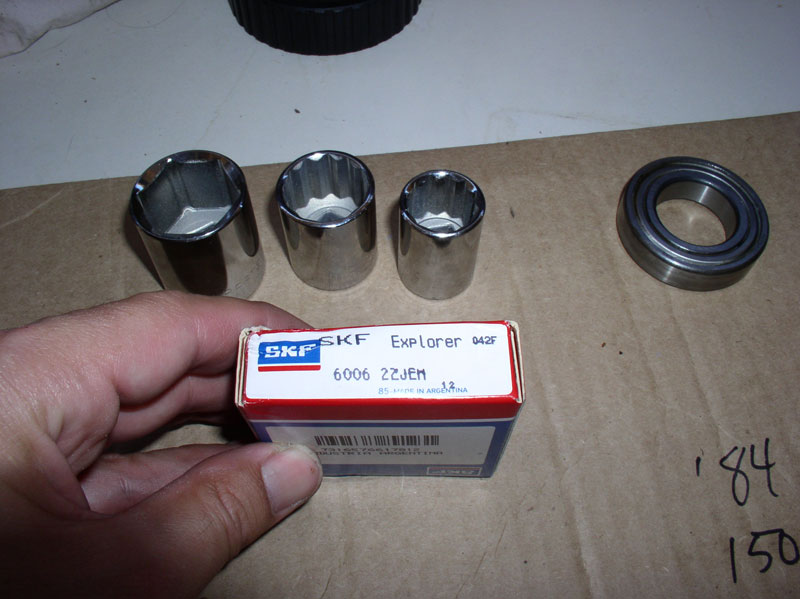
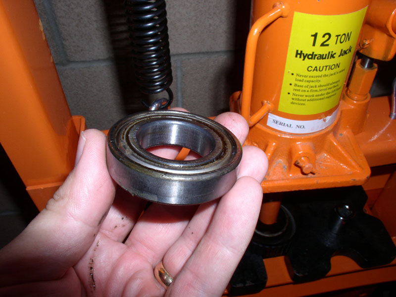
Finally, remove the bearing. This rearward bearing was the one that was causing the bearing noise on the �84 and it was obvious from the way it felt when turning � very rough and noisy.
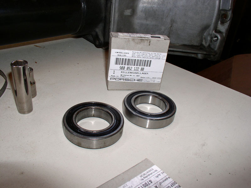
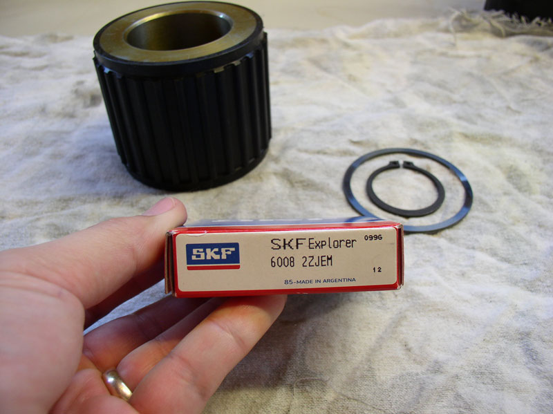
Here�s a pic of the old bearing and new bearing with the new bearing part number 900.052.122.00.
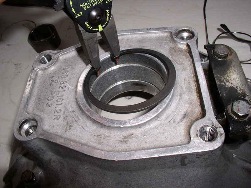
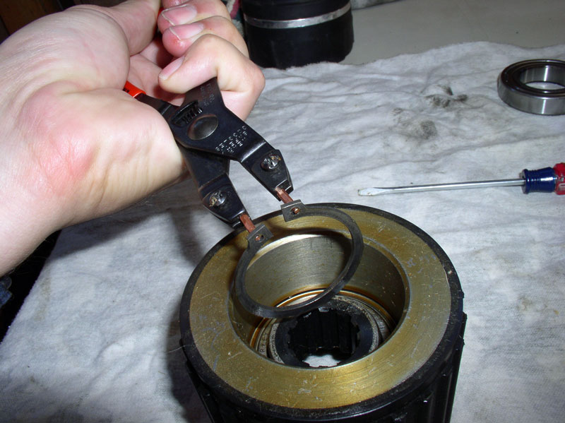
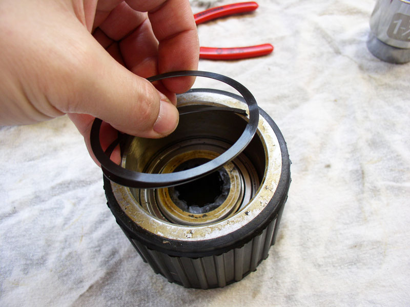
Next, I worked on removing the forward bearing from the TC housing. The bearing would need to be pressed out the front of the housing so I needed to remove the snap rings. First, remove the rearward snap ring�.
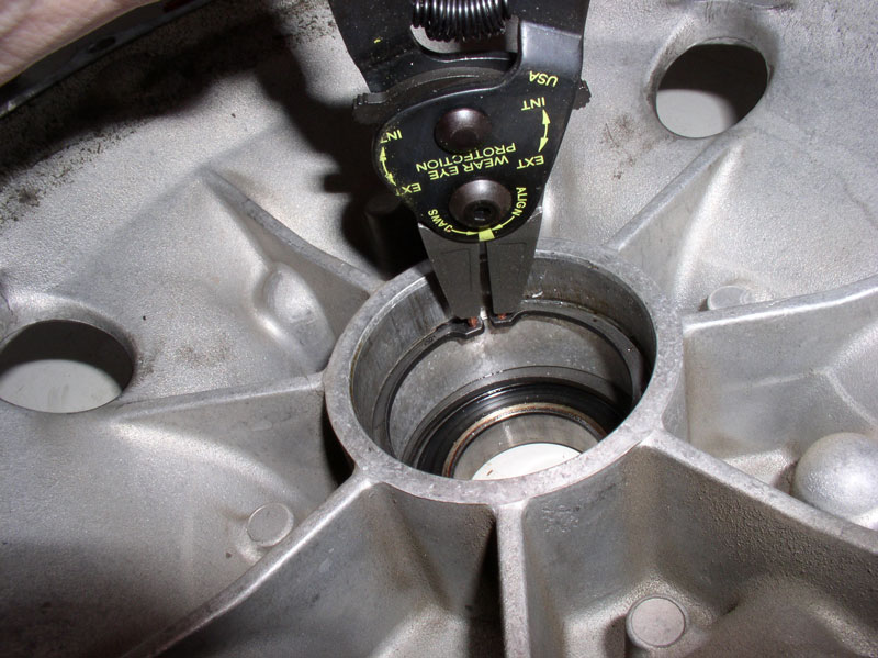
�.followed by removing the forward snap ring.
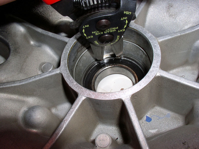
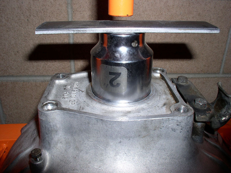
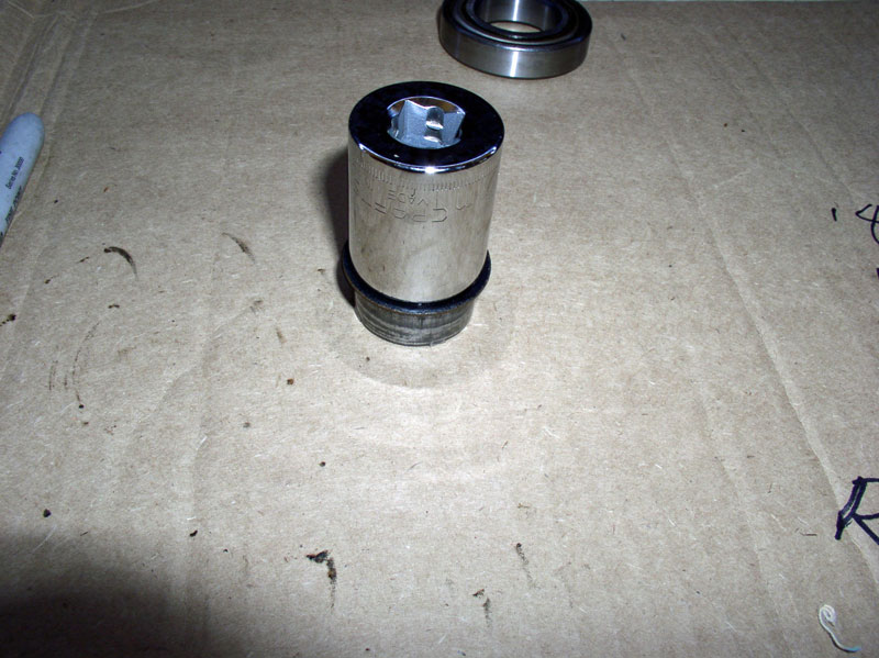
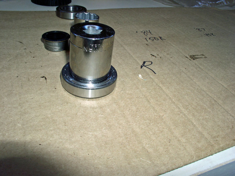
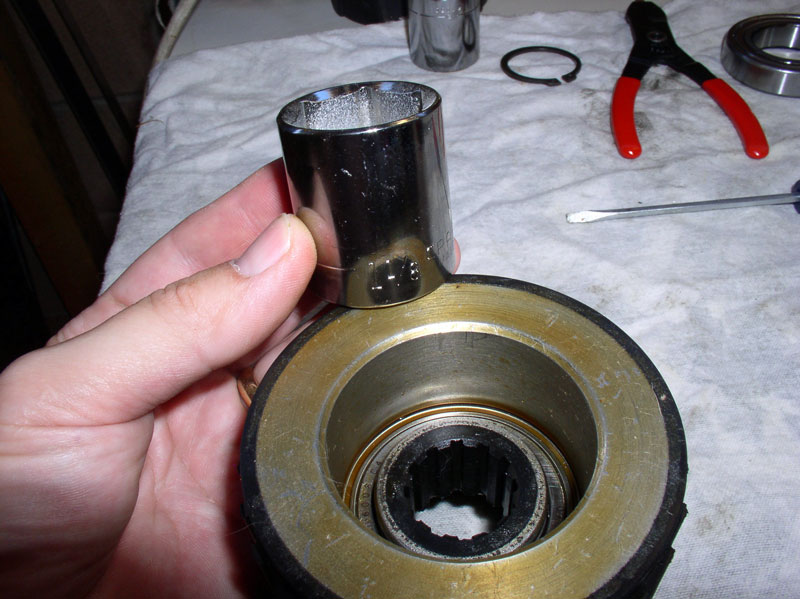
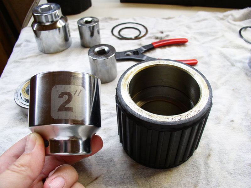
I then found an appropriately fitting socket to press the bearing out. In this case, I found a 2 inch socket that fit perfectly.
Support the TC housing on the press so the exit of the bearing is not blocked and press out the bearing.
Now you�re ready to install the new bearings and put it all back together. After wiping down the bearing surfaces on the TC housing, I installed the forward bearing first. Therefore, install the forward snap ring first.
Make sure the snap ring is fully seated in its groove.
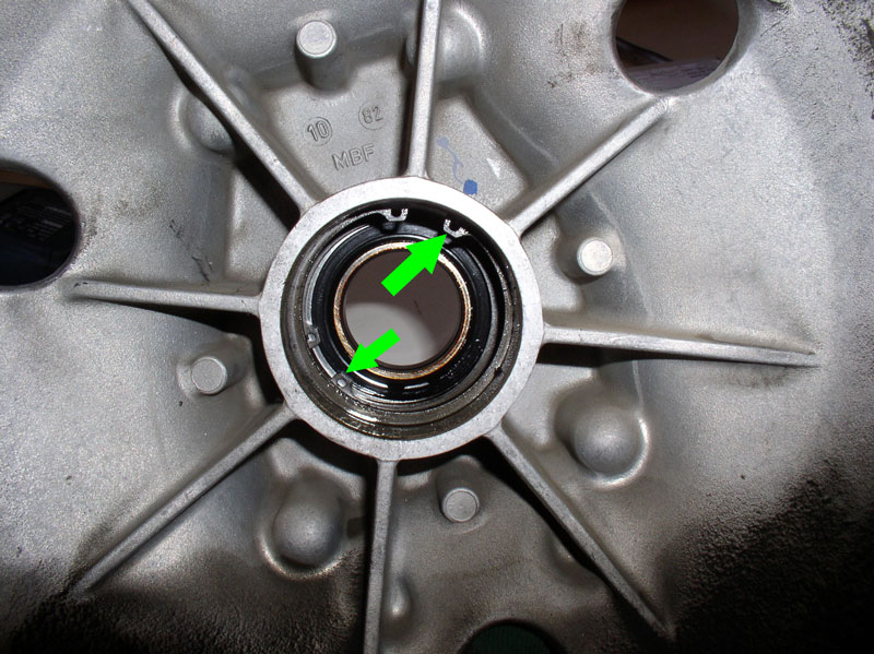
Position the bearing on the TC housing. I oriented the stamping on the bearing so they were facing forward only because the original bearings were oriented the same way. I�m not sure it makes any difference, though. As a newbie, I learned the hard way that there is one thing that does make a difference when pressing in bearings. I found there are two areas on the bearing that one can safely apply pressing force without damaging the bearing. The outer shell casing or the inner shell casing as indicated by the arrows in the pic below. Applying pressing force to the center section can easily damage the bearings � I have destroyed several bearings this way using improperly sized sockets for pressing and I�m quite good at it! The other important thing I learned was where to apply force (to the outer casing vs the inner casing). For example, if you are pressing the bearing into the TC housing like the one below, you should apply the pressing force to the outer casing (larger arrow on the right in the pic) as this is the contact surface that will meet the most resistance. Therefore, select a socket or other device that will match the diameter of the outer shell. If you were to apply pressing force to the inner bearing casing in this situation (i.e., the smaller arrow to the left in the pic), you would be applying tremendous lateral forces against the bearings themselves since the outer casing is meeting all the resistance. The bearings were not designed to withstand that kind of lateral force. I have destroyed new bearings in this manner too!
The 2 inch socket fit perfectly in the TC housing and matched the diameter of the outer bearing casing as described above. I pressed the bearing in until I met resistance (i.e., the bearing stopped against the snap ring inside the housing.
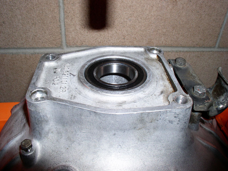
Here�s a pic of the forward bearing pressed in.
Next, I installed the rearward snap ring ensuring it is fully seated in its groove.
I then placed the collar in atop the forward bearing�..
�.placed the rearward bearing into position�.
�.and pressed it into place in the same manner as the forward bearing was pressed in.
Continued....
Here�s a pic of the old bearing and new bearing with the new bearing part number 900.052.122.00.
Next, I worked on removing the forward bearing from the TC housing. The bearing would need to be pressed out the front of the housing so I needed to remove the snap rings. First, remove the rearward snap ring�.
�.followed by removing the forward snap ring.
I then found an appropriately fitting socket to press the bearing out. In this case, I found a 2 inch socket that fit perfectly.
Support the TC housing on the press so the exit of the bearing is not blocked and press out the bearing.
Now you�re ready to install the new bearings and put it all back together. After wiping down the bearing surfaces on the TC housing, I installed the forward bearing first. Therefore, install the forward snap ring first.
Make sure the snap ring is fully seated in its groove.
Position the bearing on the TC housing. I oriented the stamping on the bearing so they were facing forward only because the original bearings were oriented the same way. I�m not sure it makes any difference, though. As a newbie, I learned the hard way that there is one thing that does make a difference when pressing in bearings. I found there are two areas on the bearing that one can safely apply pressing force without damaging the bearing. The outer shell casing or the inner shell casing as indicated by the arrows in the pic below. Applying pressing force to the center section can easily damage the bearings � I have destroyed several bearings this way using improperly sized sockets for pressing and I�m quite good at it! The other important thing I learned was where to apply force (to the outer casing vs the inner casing). For example, if you are pressing the bearing into the TC housing like the one below, you should apply the pressing force to the outer casing (larger arrow on the right in the pic) as this is the contact surface that will meet the most resistance. Therefore, select a socket or other device that will match the diameter of the outer shell. If you were to apply pressing force to the inner bearing casing in this situation (i.e., the smaller arrow to the left in the pic), you would be applying tremendous lateral forces against the bearings themselves since the outer casing is meeting all the resistance. The bearings were not designed to withstand that kind of lateral force. I have destroyed new bearings in this manner too!
The 2 inch socket fit perfectly in the TC housing and matched the diameter of the outer bearing casing as described above. I pressed the bearing in until I met resistance (i.e., the bearing stopped against the snap ring inside the housing.
Here�s a pic of the forward bearing pressed in.
Next, I installed the rearward snap ring ensuring it is fully seated in its groove.
I then placed the collar in atop the forward bearing�..
�.placed the rearward bearing into position�.
�.and pressed it into place in the same manner as the forward bearing was pressed in.
Continued....
12-19-2010, 08:08 PM
#36
Rennlist Member
Thread Starter
Join Date: Sep 2007
Location: Ridgecrest, California
Posts: 1,363
Likes: 0
Received 143 Likes
on
28 Posts
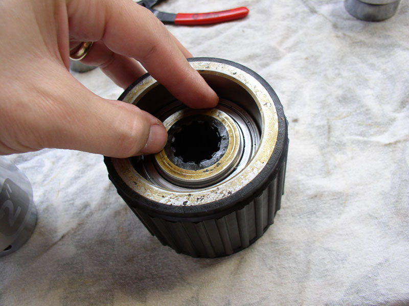
When both bearings and collar are installed, it should look like the pic below. The collar should fit snugly between the bearings but you should be able to move it around, if needed.
Next, I would press both bearings onto the drive plate shaft.
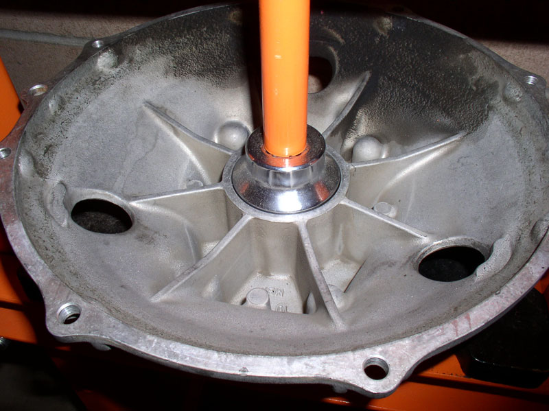
In this case, I would need to apply the pressing force to the inner bearing casing, as described earlier, since the resistance will be against the inner bearing casing. Since the collar was installed snugly between the two bearings, the force applied to the front bearing inner casing will be transmitted to the inner casing of the rear bearing casing as well thus preserving the integrity of the bearings.
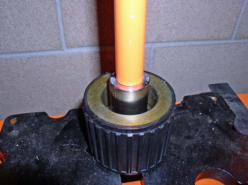
The tricky part here is finding a suitable force device since most sockets are too shallow for the drive plate shaft to move into. I found a perfectly fitting solution at Home Depot. It�s their precut and threaded 6 inch section of 1 � inch pipe. I also purchased an end cap internally threaded and threaded it onto the end of the pipe so the press would have a solid surface to press against.
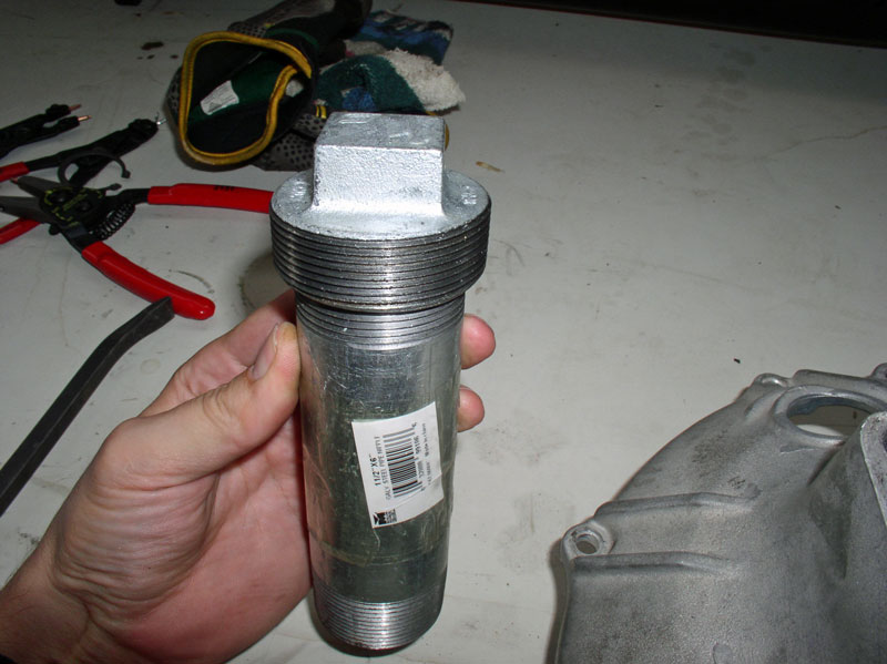
The threaded pipe diameter matches the inner bearing casing diameter and the length of the pipe allows the drive plate shaft to move freely through the bearings until it is fully seated. I used a scrap piece of plywood to provide a stable platform on the press.
I pressed the drive plate through the bearings until the TC housing bottomed out on the plywood.
I then placed one of the pressing plates under the flex plate to give enough clearance to press the drive plate shaft the rest of the way in.
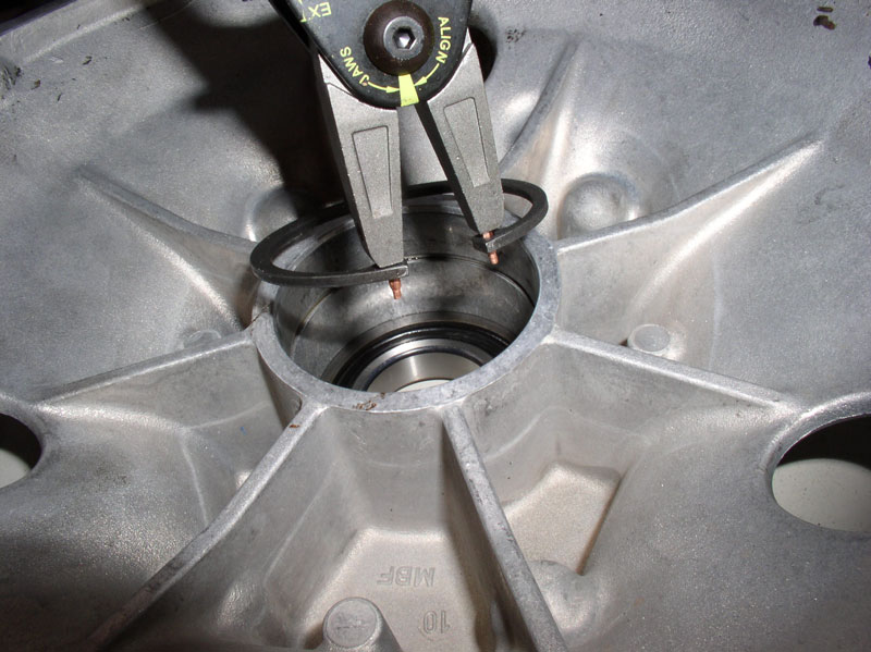
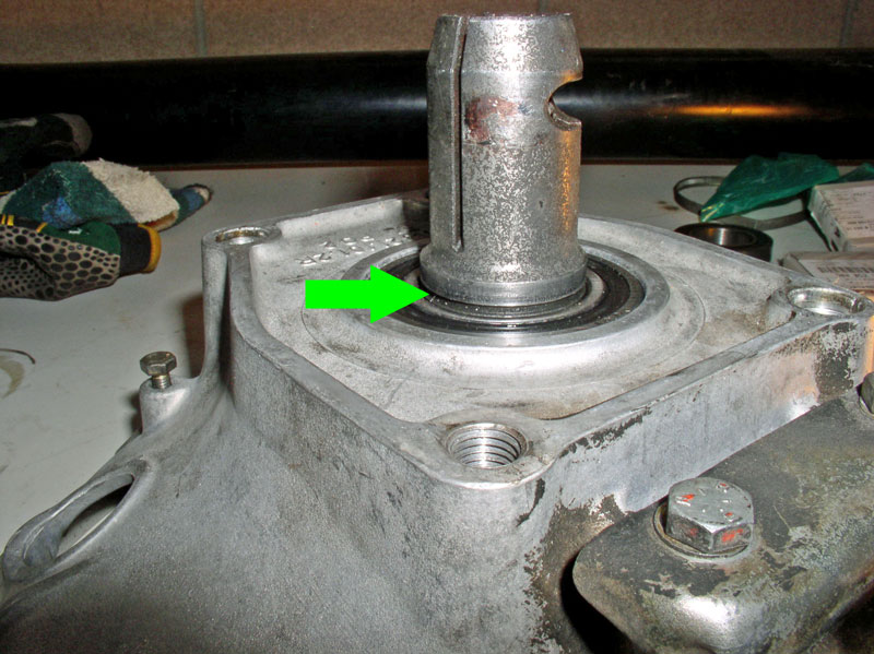
When the drive plate shaft is fully seated, you should see the snap ring groove sitting above the bearing inner casing as indicated by the arrow below.
Install the outer snap ring as shown below ensuring it is fully seated in its groove. At this point you can spin the drive plate and ensure it spins smoothly and quietly.

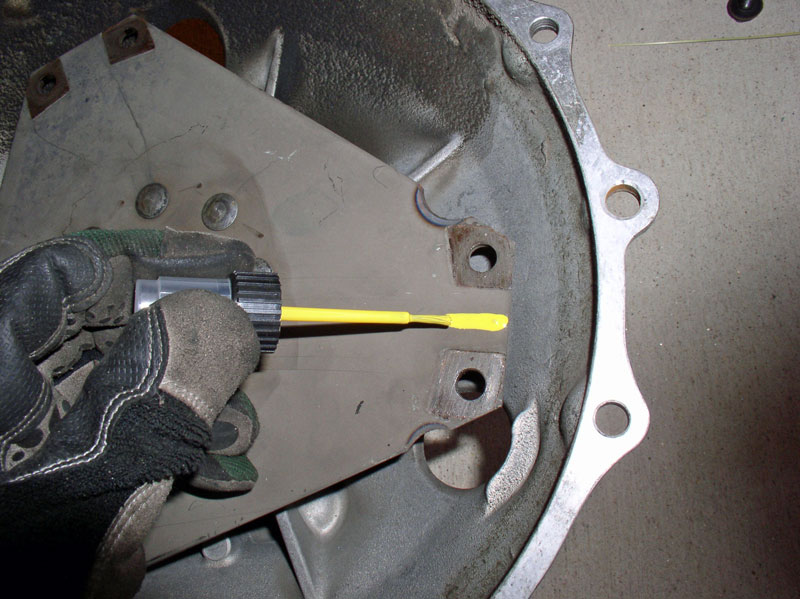
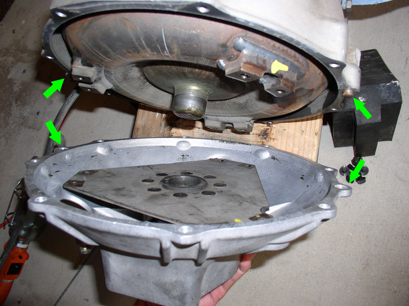
Now you�re ready to re-attach the TC housing to the transmission. I matched up the markings I made earlier (yellow paint on the TC and flex plate in the pic below). Line up the locating pins on the transmission housing with the locating holes on the TC housing as indicated by the green arrows in the pic below.
Line up the flex plate holes with the TC mounting holes and finger-tighten the 13mm bolts through the inspection holes. There are 6 bolts to install.
Then, install the 8 Allen Head bolts that secure the TC housing to the transmission housing. The bolts take a 6mm Allen Head socket. Torque to 23Nm or 17 ftlbs.
Finally, torque the six 13mm flex plate bolts to 42Nm or 33 ftlbs. Congratulations, you�ve completed the TC bearing replacement!
The OEM TT bearings are serviced in the next chapter.
Next, I would press both bearings onto the drive plate shaft.
In this case, I would need to apply the pressing force to the inner bearing casing, as described earlier, since the resistance will be against the inner bearing casing. Since the collar was installed snugly between the two bearings, the force applied to the front bearing inner casing will be transmitted to the inner casing of the rear bearing casing as well thus preserving the integrity of the bearings.
The tricky part here is finding a suitable force device since most sockets are too shallow for the drive plate shaft to move into. I found a perfectly fitting solution at Home Depot. It�s their precut and threaded 6 inch section of 1 � inch pipe. I also purchased an end cap internally threaded and threaded it onto the end of the pipe so the press would have a solid surface to press against.
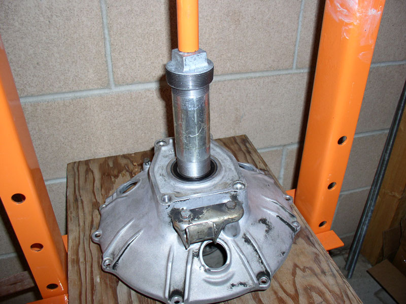
The threaded pipe diameter matches the inner bearing casing diameter and the length of the pipe allows the drive plate shaft to move freely through the bearings until it is fully seated. I used a scrap piece of plywood to provide a stable platform on the press.
I pressed the drive plate through the bearings until the TC housing bottomed out on the plywood.
I then placed one of the pressing plates under the flex plate to give enough clearance to press the drive plate shaft the rest of the way in.
When the drive plate shaft is fully seated, you should see the snap ring groove sitting above the bearing inner casing as indicated by the arrow below.
Install the outer snap ring as shown below ensuring it is fully seated in its groove. At this point you can spin the drive plate and ensure it spins smoothly and quietly.
Now you�re ready to re-attach the TC housing to the transmission. I matched up the markings I made earlier (yellow paint on the TC and flex plate in the pic below). Line up the locating pins on the transmission housing with the locating holes on the TC housing as indicated by the green arrows in the pic below.
Line up the flex plate holes with the TC mounting holes and finger-tighten the 13mm bolts through the inspection holes. There are 6 bolts to install.
Then, install the 8 Allen Head bolts that secure the TC housing to the transmission housing. The bolts take a 6mm Allen Head socket. Torque to 23Nm or 17 ftlbs.
Finally, torque the six 13mm flex plate bolts to 42Nm or 33 ftlbs. Congratulations, you�ve completed the TC bearing replacement!
The OEM TT bearings are serviced in the next chapter.
12-19-2010, 08:37 PM
#37
Rennlist Member
Thread Starter
Join Date: Sep 2007
Location: Ridgecrest, California
Posts: 1,363
Likes: 0
Received 143 Likes
on
28 Posts
CH09 SERVICING TT OEM BEARINGS
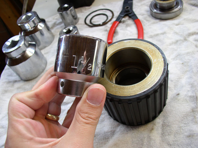
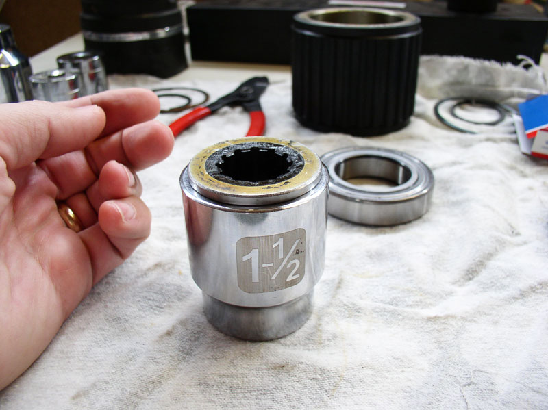
Although I did service the OEM bearings on California (�84), I strongly recommend Constantine�s Super Bearings vice using the OEM bearings. In the next chapter, I detail servicing the Super Bearings and found the components much sturdier and better design. However, if the Super Bearings are not an option, I have detailed the OEM bearing servicing in this chapter. If you go this route, you will need to purchase the OEM replacement bearings. I purchased mine from Roger Tyson at 928s R us. There were two TT bearings in California and it�s an automatic. I understand manual transmission TTs will have 3 bearings. I used various socket sizes to match the bearing and bearing insert sizes. Below is a pic of the replacement bearing.
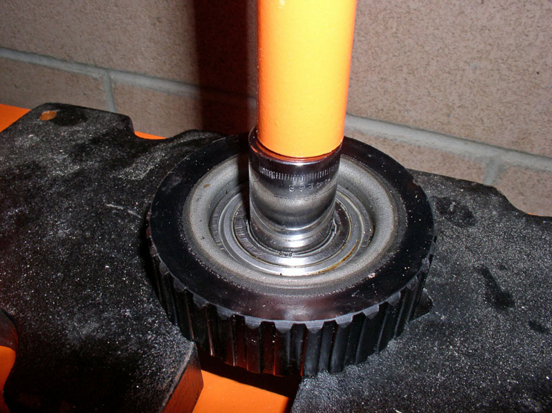
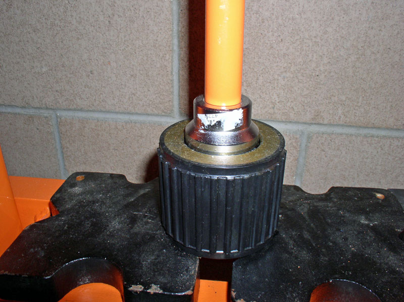
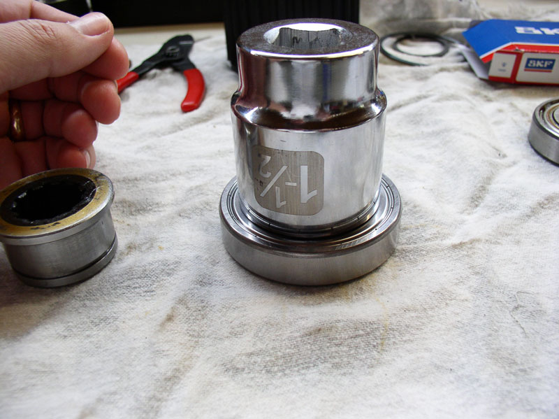
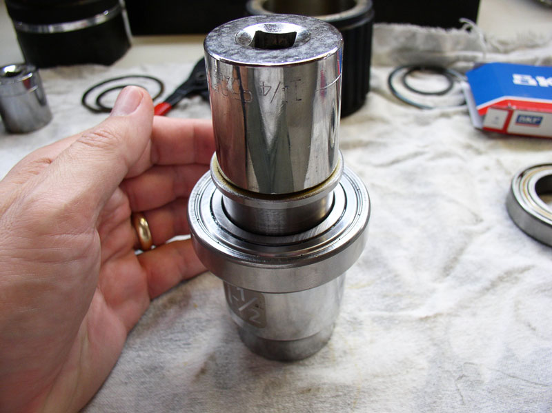
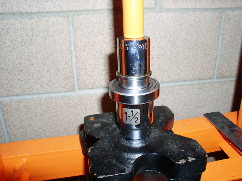
I used a shop press to press out the bearing insert. Select an appropriate sized socket that will fit inside the bearing inner shell. I found a socket that rested on the small ledge of the insert.
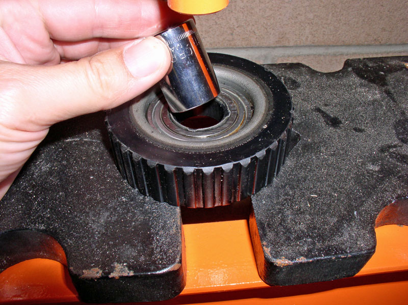
Pictured here, you can see the socket fit just inside the bearing insert. Pressing the insert out of the bearing will flatten the 4 tabs that hold the insert in place on the inner bearing shell.
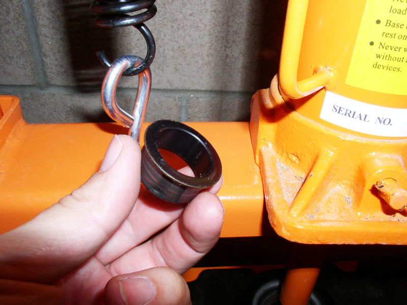
Once the insert is out, you will see it is made of a light weight metal with a rubber coating on the inside that helps grip the drive shaft (see pic below). Inspect the rubber coating for damage. If it is damaged, peeling or torn, consider replacing the insert. I believe the part is NLA but have heard there may be alternative materials available. This insert looked like it was in great shape to be used again.
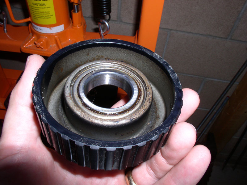
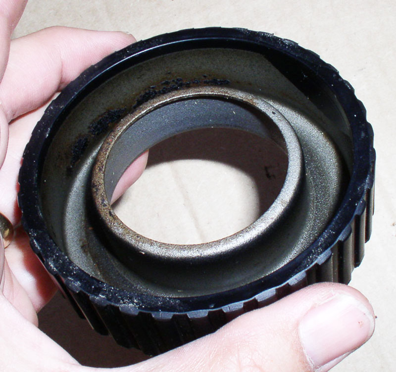
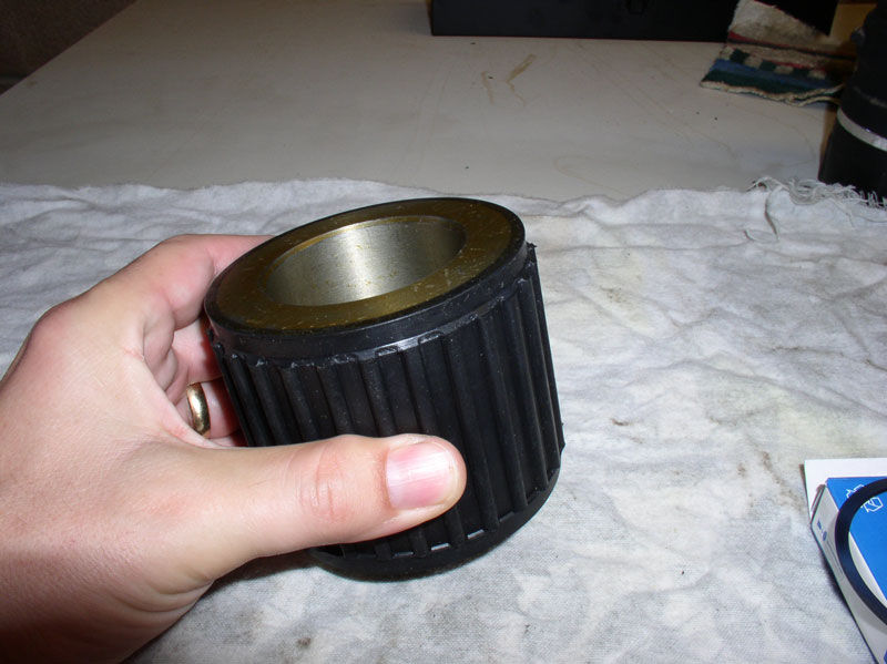
Once the insert is removed, you can press out the bearing from the carrier. The carrier pictured below is showing the forward facing side of the carrier (facing the engine when installed in the TT). For easier reference I call this the front side of the carrier. You will press the bearing out toward the rear of the carrier.
I used a bearing installer on the shop press to press out the bearing from the carrier.
Here�s a pic of the bearing once removed from the carrier.
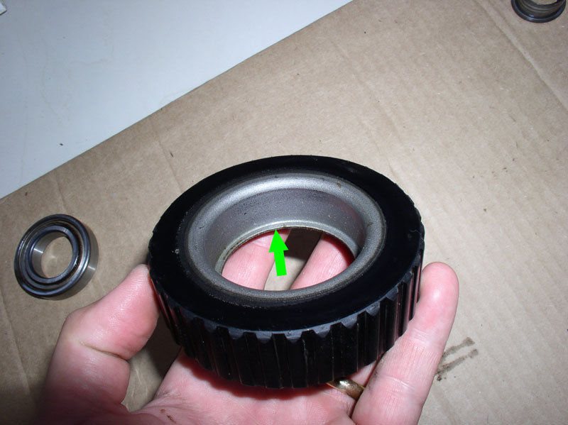
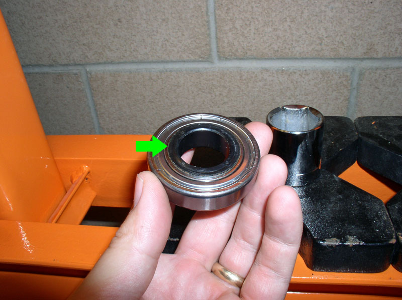
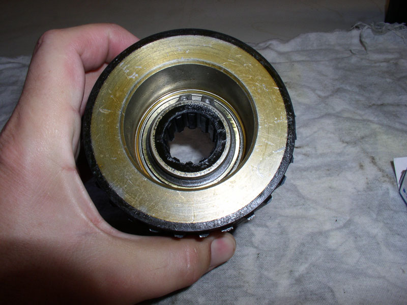
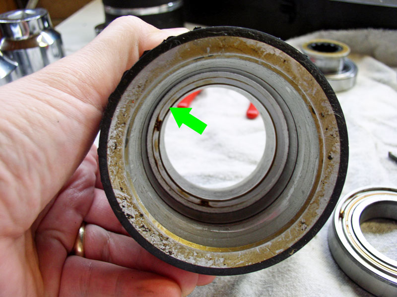
After the bearing is removed from the carrier and the carrier is cleaned up a bit, it is easier to see how the new bearing will fit into the carrier. It will be pressed in from the back of the carrier and pressed in all the way until the bearing rests against the lip identified by the green arrow in the picture below.
Here�s a close up of the front side of the bearing carrier. The rubber coating still looks pretty good.
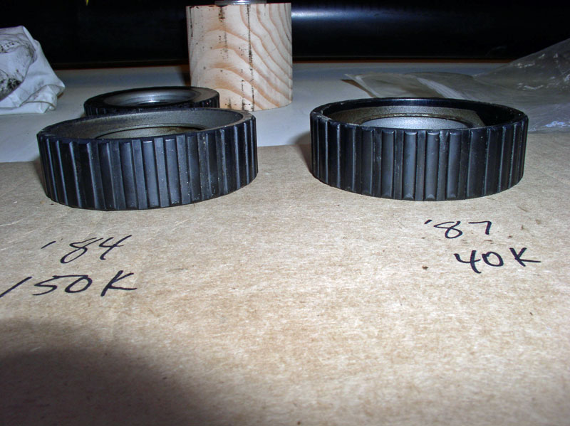
I had both California and Virginia�s bearing carriers out and compared them side by side. Even though California has nearly quadruple the mileage as Virginia, the carrier looked very similar.
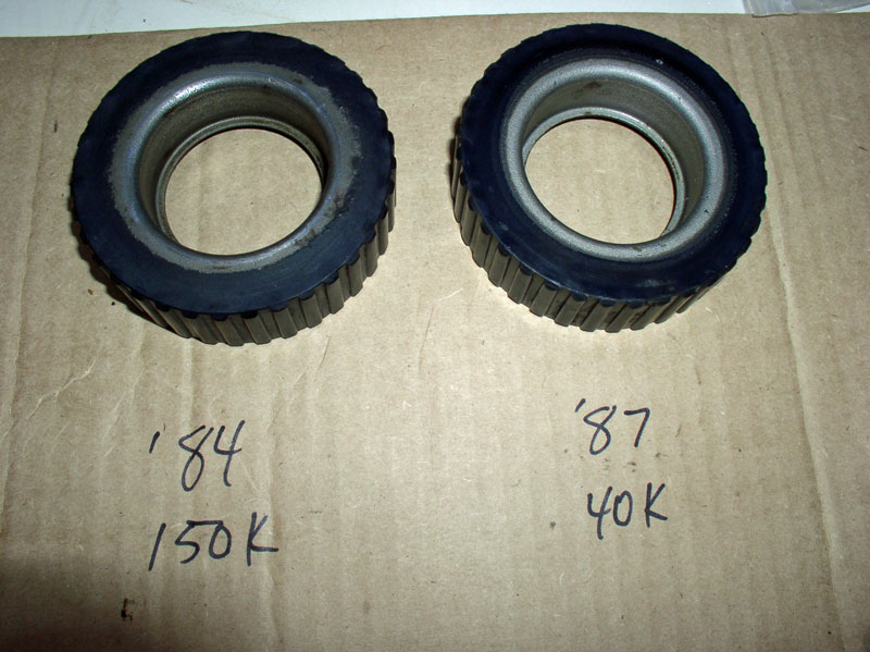
Both carriers were firmly attached inside their respective TT when removed and had not wondered around.
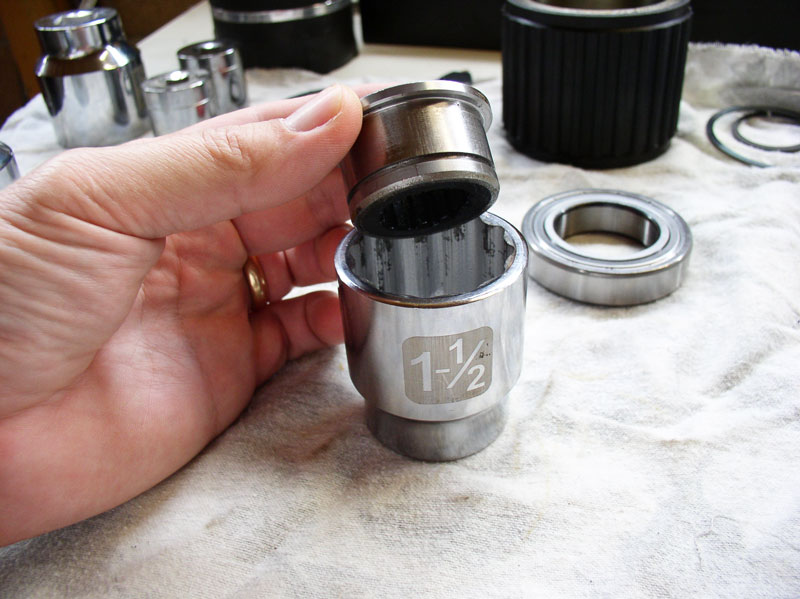
I began the reassembly process by first installing the insert into the bearing then installing the bearing into the carrier. I found a suitably sized socket to fit on top of the insert flange as shown in the pic below.
Since the insert will be pressed in the center of the bearing, the inner bearing shell will encounter the resistance. Therefore, I needed a socket that would fit just on the inner shell and no larger. The socket also needed to be large enough as to not interfere with the insert as it comes through. The bearing insert actually stands out slightly on the rear of the bearing when it is fully pressed in.
Assemble the two sockets on the press as shown making sure the sockets are correctly aligned.
Press the insert all the way down until it is flush against the inner bearing shell as shown below.
Continued....
Although I did service the OEM bearings on California (�84), I strongly recommend Constantine�s Super Bearings vice using the OEM bearings. In the next chapter, I detail servicing the Super Bearings and found the components much sturdier and better design. However, if the Super Bearings are not an option, I have detailed the OEM bearing servicing in this chapter. If you go this route, you will need to purchase the OEM replacement bearings. I purchased mine from Roger Tyson at 928s R us. There were two TT bearings in California and it�s an automatic. I understand manual transmission TTs will have 3 bearings. I used various socket sizes to match the bearing and bearing insert sizes. Below is a pic of the replacement bearing.
I used a shop press to press out the bearing insert. Select an appropriate sized socket that will fit inside the bearing inner shell. I found a socket that rested on the small ledge of the insert.
Pictured here, you can see the socket fit just inside the bearing insert. Pressing the insert out of the bearing will flatten the 4 tabs that hold the insert in place on the inner bearing shell.
Once the insert is out, you will see it is made of a light weight metal with a rubber coating on the inside that helps grip the drive shaft (see pic below). Inspect the rubber coating for damage. If it is damaged, peeling or torn, consider replacing the insert. I believe the part is NLA but have heard there may be alternative materials available. This insert looked like it was in great shape to be used again.
Once the insert is removed, you can press out the bearing from the carrier. The carrier pictured below is showing the forward facing side of the carrier (facing the engine when installed in the TT). For easier reference I call this the front side of the carrier. You will press the bearing out toward the rear of the carrier.
I used a bearing installer on the shop press to press out the bearing from the carrier.
Here�s a pic of the bearing once removed from the carrier.
After the bearing is removed from the carrier and the carrier is cleaned up a bit, it is easier to see how the new bearing will fit into the carrier. It will be pressed in from the back of the carrier and pressed in all the way until the bearing rests against the lip identified by the green arrow in the picture below.
Here�s a close up of the front side of the bearing carrier. The rubber coating still looks pretty good.
I had both California and Virginia�s bearing carriers out and compared them side by side. Even though California has nearly quadruple the mileage as Virginia, the carrier looked very similar.
Both carriers were firmly attached inside their respective TT when removed and had not wondered around.
I began the reassembly process by first installing the insert into the bearing then installing the bearing into the carrier. I found a suitably sized socket to fit on top of the insert flange as shown in the pic below.
Since the insert will be pressed in the center of the bearing, the inner bearing shell will encounter the resistance. Therefore, I needed a socket that would fit just on the inner shell and no larger. The socket also needed to be large enough as to not interfere with the insert as it comes through. The bearing insert actually stands out slightly on the rear of the bearing when it is fully pressed in.
Assemble the two sockets on the press as shown making sure the sockets are correctly aligned.
Press the insert all the way down until it is flush against the inner bearing shell as shown below.
Continued....
12-19-2010, 08:40 PM
#38
Rennlist Member
Thread Starter
Join Date: Sep 2007
Location: Ridgecrest, California
Posts: 1,363
Likes: 0
Received 143 Likes
on
28 Posts
The bearing will be pressed into the carrier from the back side with the bearing oriented as shown below.
I found a 1 � inch socket that matched the diameter of the outer bearing shell perfectly. An appropriately sized socket will ensure the pressing force will be applied to the outer bearing shell only and preserve the integrity of the bearing. I destroyed a bearing previously by using a socket that was smaller than the diameter of the outer shell and it pressed in on the bearing itself.
Press the bearing in until it is resting flush against the carrier lip as shown below.
Finally, I attempted to push out the 4 locking tabs on the insert. I used a set of reverse pliers to �push out� the tabs at least enough to help hold the insert in place while it is in operation.
Super Bearing servicing is discussed in the next chapter.
12-19-2010, 09:08 PM
#39
Rennlist Member
Thread Starter
Join Date: Sep 2007
Location: Ridgecrest, California
Posts: 1,363
Likes: 0
Received 143 Likes
on
28 Posts
CH10 SERVICING TT SUPER BEARINGS
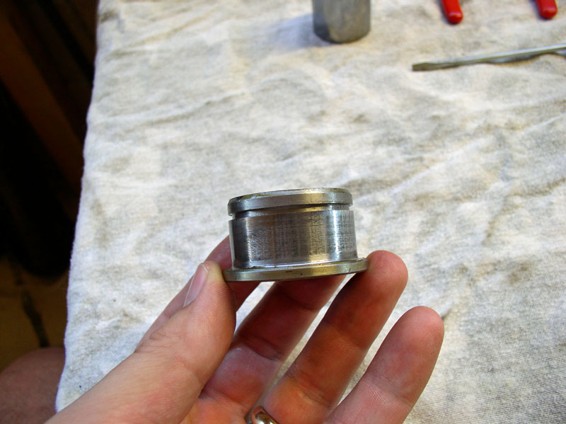
In a recent conversation with Constantine, he mentioned it is possible to service is Super Bearings. I had a set of his Super Bearings and he provided me with an updated bearing kit to perform the service. With Constantine�s permission, I�ve included some pictures of how I serviced the bearing in this chapter. The Super Bearing carrier is massively impressive when compared to the OEM bearing carrier as pictured below.
It is designed with an insert like the OEM bearing but the insert is much more substantial and has a grooved rubber coating to grip the drive shaft. The pic below shows the rearward facing end of the Super Bearing. You can also see the snap ring � it locks the insert in place within the center of the bearing.
The pic below is of the forward facing end of the Super Bearing (the end facing the engine). You will notice a spiro-lock ring indicated by the green arrow. This ring locks the bearing securely in the carrier.

Here�s a picture of the service kit I received from Constantine. It contains the replacement bearing, a new spiro-lock ring and a new snap ring for the insert.
First, to disassemble the Super Bearing, I removed the drive shaft insert from the bearing then I removed the bearing from the carrier. To remove the insert, remove the snap ring from the insert as shown below. You will pres out the insert from the same side as you remove the snap ring.
The insert will be pressed out from the rear of the carrier toward the front side. I found a 1 1/8 inch socket that fit the back end of the insert.
I used a shop press to press the bearing insert out.
When the insert is removed, you will notice it is substantially heavier duty than the thin metal insert found in the OEM bearings. Here you can see the flange used to stop the insert when pressing it into the bearing as well as the groove for the snap ring.
Next, I removed the bearing from the carrier. To do this, I removed the spiro-lock ring from the carrier groove. The spiro-lock ring has a tapered end that you can easily fit a flat blade screw driver behind and lever it out of its groove in the carrier.
Once the end is out far enough, I simply grasp the end with my fingers and followed the ring around the inside of the carrier to carefully pull out the ring from the groove�.
�until the entire ring was out.
The bearing will be pressed out of the carrier from the rear of the carrier. I found a 1 � socket fit perfectly inside the carrier and suitable for pressing out the bearing.
I used the shop press and socket to press out the bearing.
Once the bearing is out, you will see the inside of the Super Bearing carrier has a lip where the bearing is pressed against when installing the new bearing.
To press the drive shaft insert into the bearing without damaging the bearing, I needed to find a socket that the insert would fit into.
Continued....
In a recent conversation with Constantine, he mentioned it is possible to service is Super Bearings. I had a set of his Super Bearings and he provided me with an updated bearing kit to perform the service. With Constantine�s permission, I�ve included some pictures of how I serviced the bearing in this chapter. The Super Bearing carrier is massively impressive when compared to the OEM bearing carrier as pictured below.
It is designed with an insert like the OEM bearing but the insert is much more substantial and has a grooved rubber coating to grip the drive shaft. The pic below shows the rearward facing end of the Super Bearing. You can also see the snap ring � it locks the insert in place within the center of the bearing.
The pic below is of the forward facing end of the Super Bearing (the end facing the engine). You will notice a spiro-lock ring indicated by the green arrow. This ring locks the bearing securely in the carrier.
Here�s a picture of the service kit I received from Constantine. It contains the replacement bearing, a new spiro-lock ring and a new snap ring for the insert.
First, to disassemble the Super Bearing, I removed the drive shaft insert from the bearing then I removed the bearing from the carrier. To remove the insert, remove the snap ring from the insert as shown below. You will pres out the insert from the same side as you remove the snap ring.
The insert will be pressed out from the rear of the carrier toward the front side. I found a 1 1/8 inch socket that fit the back end of the insert.
I used a shop press to press the bearing insert out.
When the insert is removed, you will notice it is substantially heavier duty than the thin metal insert found in the OEM bearings. Here you can see the flange used to stop the insert when pressing it into the bearing as well as the groove for the snap ring.
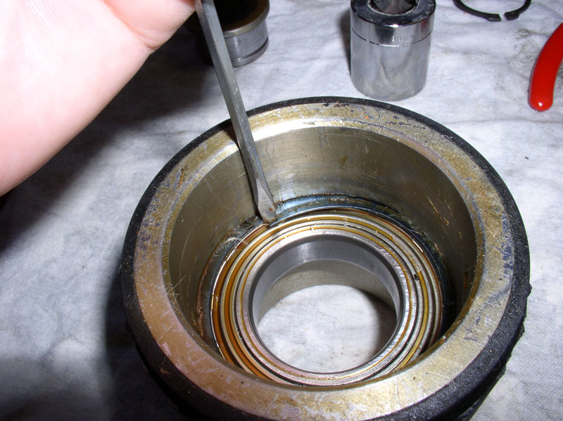
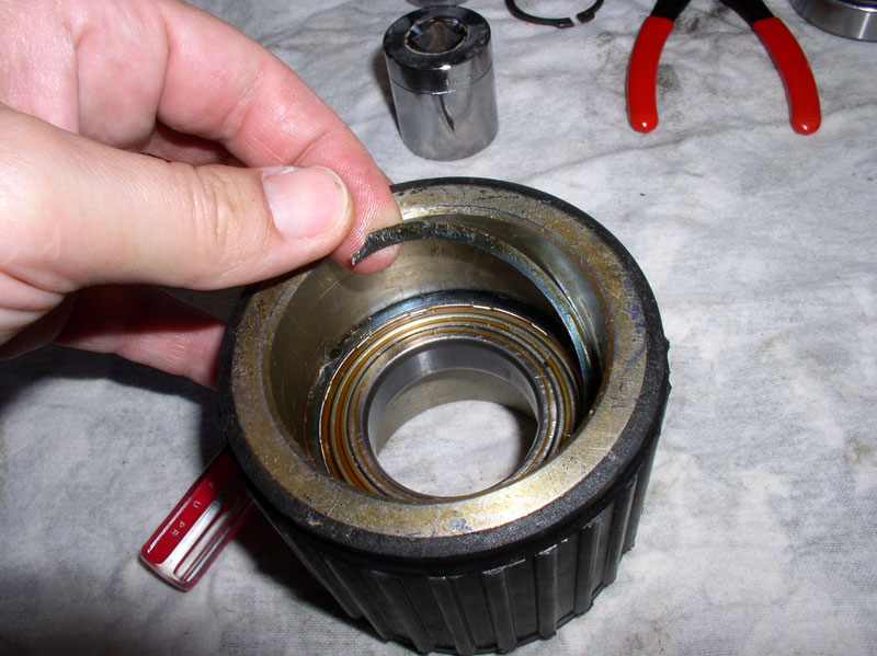
Next, I removed the bearing from the carrier. To do this, I removed the spiro-lock ring from the carrier groove. The spiro-lock ring has a tapered end that you can easily fit a flat blade screw driver behind and lever it out of its groove in the carrier.
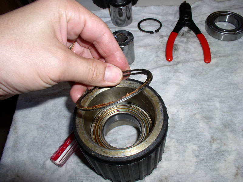
Once the end is out far enough, I simply grasp the end with my fingers and followed the ring around the inside of the carrier to carefully pull out the ring from the groove�.
�until the entire ring was out.
The bearing will be pressed out of the carrier from the rear of the carrier. I found a 1 � socket fit perfectly inside the carrier and suitable for pressing out the bearing.
I used the shop press and socket to press out the bearing.
Once the bearing is out, you will see the inside of the Super Bearing carrier has a lip where the bearing is pressed against when installing the new bearing.
To press the drive shaft insert into the bearing without damaging the bearing, I needed to find a socket that the insert would fit into.
Continued....
12-19-2010, 09:15 PM
#40
Rennlist Member
Thread Starter
Join Date: Sep 2007
Location: Ridgecrest, California
Posts: 1,363
Likes: 0
Received 143 Likes
on
28 Posts
Since the insert protrudes from the bearing when fully seated, I found a socket that will allow the inert to pass through the bearing without interference coming out the opposite side.
The same socket diameter needed to match the diameter of the bearing inner shell casing since this is the surface that will encounter the friction when pressing in the insert.
Here�s the set up I went with in the pic below.
I placed the assembly on the shop press and ensured the sockets were aligned and pressed the drive shaft insert into the bearing.
When the insert is fully pressed into the bearing, it should look like the pic below.
Next, install the snap ring that will lock the insert into the bearing. Ensure the snap ring is fully seated in the groove of the insert as shown in the pic below.
To press the bearing into the carrier, I used a large socket that matched the diameter of the bearing outer shell casing.
Place the bearing/insert assembly into the carrier from the forward facing side as shown.
Press the bearing into the carrier until it is fully seated.
When the bearing is fully seated against the stop in the carrier, you should be able to see the groove in the carrier for the spiro-lock ring as indicated by the green arrow in the pic below.
Install the spiro-lock ring next. I started by spreading the ring apart slightly and inserting one end of the ring into the groove first then followed the ring around with my finger to press the rest of the ring in as I went.
When the spiro-lock ring is fully inserted into the groove in the carrier, it should look like the pic below. One final step is recommended before installing the Super Bearing into the TT. Constantine recommends spraying the insides of both front and rear of the bearing and carrier with a corrosion inhibiter that is available at stores that sell marine parts and supplies. CRC �Heavy Duty Corrosion Inhibitor� is a brand that works and may be easier to find. You can see from the pic below the insides of the carrier and the insert still have most of the inhibitor applied that came with the Super Bearing new. Do not apply the inhibitor to the outside rubber part of the Super Bearing.
Congratulations! Your Super Bearing is serviced and ready to put into operation.
12-19-2010, 09:33 PM
#41
Rennlist Member
Thread Starter
Join Date: Sep 2007
Location: Ridgecrest, California
Posts: 1,363
Likes: 0
Received 143 Likes
on
28 Posts
CH11 INSTALLING TT BEARINGS
The process described in this chapter for installing the Super Bearings can also be used for installing the OEM bearing carriers with the exception of the bearing spacing measurements and installation of the vibration damper (these are not covered here). If you are installing the OEM carriers, you will want to install the bearings and vibration damper to the factory recommended spacing.
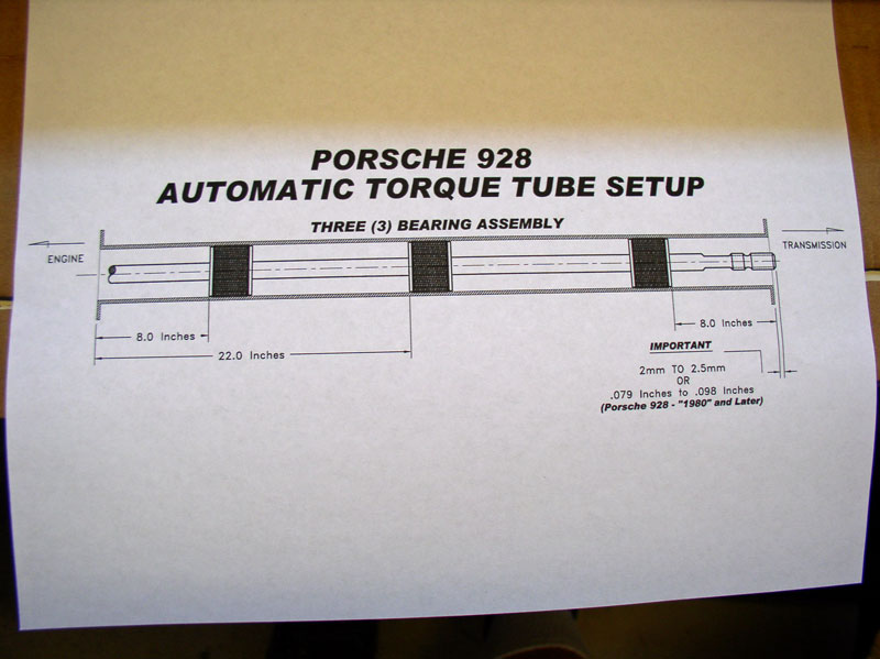
I installed 3 of Constantine�s Super Bearings in the TT that replaced the existing 2 OEM bearings and the vibration damper. Constantine provides a detailed set of instructions and the diagram below for both 2 and 3 bearing installation measurements. As you can see below, for the 3 bearing assembly, the front and rear bearings are installed 8 inches from the ends of the TT while the middle bearing is installed 22 inches from the front (engine end) of the TT.
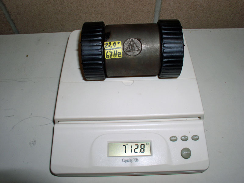
Constantine suggested I could simply delete the vibration damper in favor of using 3 Super Bearings. I asked Constantine about the weight differences between the OEM bearings and vibration damper and he indicated the weight of the two rear Super Bearings would approximately match the weight of the vibration damper (especially since I had one of the earlier Super Bearings that had a heavier carrier). He also mentioned that the rubber ends of the vibration damper can separate from the metal center weight and cause issues with the center weight moving about freely within the TT. Although the rubber ends of the vibration damper on Virginia (�87 with 40K miles) were solidly attached, the rubber ends on California�s vibration damper (�84 with 153K miles) detached easily from the center weight. Therefore, I decided to go ahead and delete the vibration damper in favor of using 3 Super Bearings. You can see in the pic below the vibration damper weighed 7 lbs 12.8 ounces.
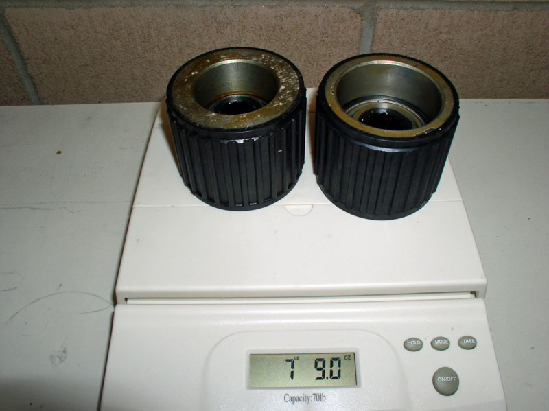
I weighed the center and rear Super Bearings I would be using in the TT and found the weight difference between the vibration damper and the new Super Bearings to be only a few ounces. The earlier, heavier Super Bearing is on the left. Constantine recommended placing the earlier, heavier Super Bearing at the rear of the TT, which I did. I�m not an engineering expert but these bearings are tremendously Beefy compared to the OEM bearings/carriers and I�m very impressed with the workmanship and quality of their design. Well done, Constantine!
The Super Bearings will be oriented in the TT with the side that contains the spiro-lock ring facing forward toward the engine as shown in the picture below.
Using the recommended spacing measurements for the Super Bearings and the approximate placement of the drive shaft, the bearing and drive shaft set up should look something very close to what is pictured below when installed.
I used the same wooden shuttle I made for extracting the OEM bearings for the installation of the Super Bearings. However, this shuttle is overkill for the installation due to the design of the Super Bearing. Constantine provides a wooden disk about 3 � inches in diameter that works well for installing the Super Bearings. Due to the extra length of the Super Bearing carrier, it is impossible for the Super Bearing to get �crosswise� inside the TT when installing � another nice design advantage of Constantine�s bearings. I made the extra thick wooden shuttle to assist in the installation of OEM bearing carriers since they are only about 1 inch wide and can get �crosswise� installed in the TT � the extra thick wooden shuttle makes installing OEM carriers virtually impossible to install �crosswise�. Since my wooden shuttle is approximately 3 � inches thick, I would need to take this into account when installing the Super Bearings at the correct spacing.
I planned to install the rear Super Bearing first from the rear of the TT and I would install the center and front Super Bearings from the front of the TT. I did not apply any lubricant to the inside of the TT since I�d be using the threaded rod for the installation. I did, however, clean the inside of the TT with a degreaser earlier to ensure the Super Bearings would be firmly seated when installed. I placed the rear Super Bearing in the proper orientation at the rear of the TT�.
�.and pressed the bearing into the TT as far as I could.
I then placed the threaded rod I used to extract the OEM bearings earlier into the TT and through the Super Bearing. I mounted the wooden shuttle on the threaded rod and installed the washer and nut. As mentioned earlier, you could also use the wooden disk supplied with Constantine�s Super Bearings instead of the wooden shuttle pictured below.
At the other end of the TT, I mounted the 2 X 6, washers and locknuts as seen in the picture below and stared tightening the nut next to the 2 X 6 while counter holding the lock nuts at the end of the threaded rod. This method �pulls� the Super Bearing through the TT and provides effortless and fine control on where to place the bearing without the use of percussion instruments. If you really want to be scientific about it, you can measure the remaining distance in inches to go for bearing placement and multiply by 11 to get the number of remaining �turns� of the tightening nut since the threaded rod used below is 11 threads per inch.
When the distance from the end of the TT to the wooden shuttle reached 4 � inches (plus the thickness of the shuttle of 3 � inches), the Super Bearing was in proper position � 8 inches from the rear of the TT.
Remove the threaded rod and confirm the measurements. The Super Bearing installed should look something like the pic below.
Next, prepare the center Super Bearing for installation. Place it at the front of the TT with the spiro-lock ring facing forward toward the engine as pictured below and press it into place.
Install the threaded rod as before and pictured below.
And repeat the �pulling� process until the measurement from the front of the TT to the wooden shuttle is 18 � inches (plus the 3 � inches of shuttle thickness) and the center bearing will be in proper position at 22 inches from the front of the TT.
Continued....
The process described in this chapter for installing the Super Bearings can also be used for installing the OEM bearing carriers with the exception of the bearing spacing measurements and installation of the vibration damper (these are not covered here). If you are installing the OEM carriers, you will want to install the bearings and vibration damper to the factory recommended spacing.
I installed 3 of Constantine�s Super Bearings in the TT that replaced the existing 2 OEM bearings and the vibration damper. Constantine provides a detailed set of instructions and the diagram below for both 2 and 3 bearing installation measurements. As you can see below, for the 3 bearing assembly, the front and rear bearings are installed 8 inches from the ends of the TT while the middle bearing is installed 22 inches from the front (engine end) of the TT.
Constantine suggested I could simply delete the vibration damper in favor of using 3 Super Bearings. I asked Constantine about the weight differences between the OEM bearings and vibration damper and he indicated the weight of the two rear Super Bearings would approximately match the weight of the vibration damper (especially since I had one of the earlier Super Bearings that had a heavier carrier). He also mentioned that the rubber ends of the vibration damper can separate from the metal center weight and cause issues with the center weight moving about freely within the TT. Although the rubber ends of the vibration damper on Virginia (�87 with 40K miles) were solidly attached, the rubber ends on California�s vibration damper (�84 with 153K miles) detached easily from the center weight. Therefore, I decided to go ahead and delete the vibration damper in favor of using 3 Super Bearings. You can see in the pic below the vibration damper weighed 7 lbs 12.8 ounces.
I weighed the center and rear Super Bearings I would be using in the TT and found the weight difference between the vibration damper and the new Super Bearings to be only a few ounces. The earlier, heavier Super Bearing is on the left. Constantine recommended placing the earlier, heavier Super Bearing at the rear of the TT, which I did. I�m not an engineering expert but these bearings are tremendously Beefy compared to the OEM bearings/carriers and I�m very impressed with the workmanship and quality of their design. Well done, Constantine!
The Super Bearings will be oriented in the TT with the side that contains the spiro-lock ring facing forward toward the engine as shown in the picture below.
Using the recommended spacing measurements for the Super Bearings and the approximate placement of the drive shaft, the bearing and drive shaft set up should look something very close to what is pictured below when installed.
I used the same wooden shuttle I made for extracting the OEM bearings for the installation of the Super Bearings. However, this shuttle is overkill for the installation due to the design of the Super Bearing. Constantine provides a wooden disk about 3 � inches in diameter that works well for installing the Super Bearings. Due to the extra length of the Super Bearing carrier, it is impossible for the Super Bearing to get �crosswise� inside the TT when installing � another nice design advantage of Constantine�s bearings. I made the extra thick wooden shuttle to assist in the installation of OEM bearing carriers since they are only about 1 inch wide and can get �crosswise� installed in the TT � the extra thick wooden shuttle makes installing OEM carriers virtually impossible to install �crosswise�. Since my wooden shuttle is approximately 3 � inches thick, I would need to take this into account when installing the Super Bearings at the correct spacing.
I planned to install the rear Super Bearing first from the rear of the TT and I would install the center and front Super Bearings from the front of the TT. I did not apply any lubricant to the inside of the TT since I�d be using the threaded rod for the installation. I did, however, clean the inside of the TT with a degreaser earlier to ensure the Super Bearings would be firmly seated when installed. I placed the rear Super Bearing in the proper orientation at the rear of the TT�.
�.and pressed the bearing into the TT as far as I could.
I then placed the threaded rod I used to extract the OEM bearings earlier into the TT and through the Super Bearing. I mounted the wooden shuttle on the threaded rod and installed the washer and nut. As mentioned earlier, you could also use the wooden disk supplied with Constantine�s Super Bearings instead of the wooden shuttle pictured below.
At the other end of the TT, I mounted the 2 X 6, washers and locknuts as seen in the picture below and stared tightening the nut next to the 2 X 6 while counter holding the lock nuts at the end of the threaded rod. This method �pulls� the Super Bearing through the TT and provides effortless and fine control on where to place the bearing without the use of percussion instruments. If you really want to be scientific about it, you can measure the remaining distance in inches to go for bearing placement and multiply by 11 to get the number of remaining �turns� of the tightening nut since the threaded rod used below is 11 threads per inch.
When the distance from the end of the TT to the wooden shuttle reached 4 � inches (plus the thickness of the shuttle of 3 � inches), the Super Bearing was in proper position � 8 inches from the rear of the TT.
Remove the threaded rod and confirm the measurements. The Super Bearing installed should look something like the pic below.
Next, prepare the center Super Bearing for installation. Place it at the front of the TT with the spiro-lock ring facing forward toward the engine as pictured below and press it into place.
Install the threaded rod as before and pictured below.
And repeat the �pulling� process until the measurement from the front of the TT to the wooden shuttle is 18 � inches (plus the 3 � inches of shuttle thickness) and the center bearing will be in proper position at 22 inches from the front of the TT.
Continued....
12-19-2010, 09:35 PM
#42
Rennlist Member
Thread Starter
Join Date: Sep 2007
Location: Ridgecrest, California
Posts: 1,363
Likes: 0
Received 143 Likes
on
28 Posts
Finally, repeat the process one more time, removing the threaded rod and installing the forward Super Bearing and �pull� it into place as shown below.
Remove the threaded rod and confirm the proper spacing measurement. In this case, the forward bearing is 8 inches from the front of the TT.
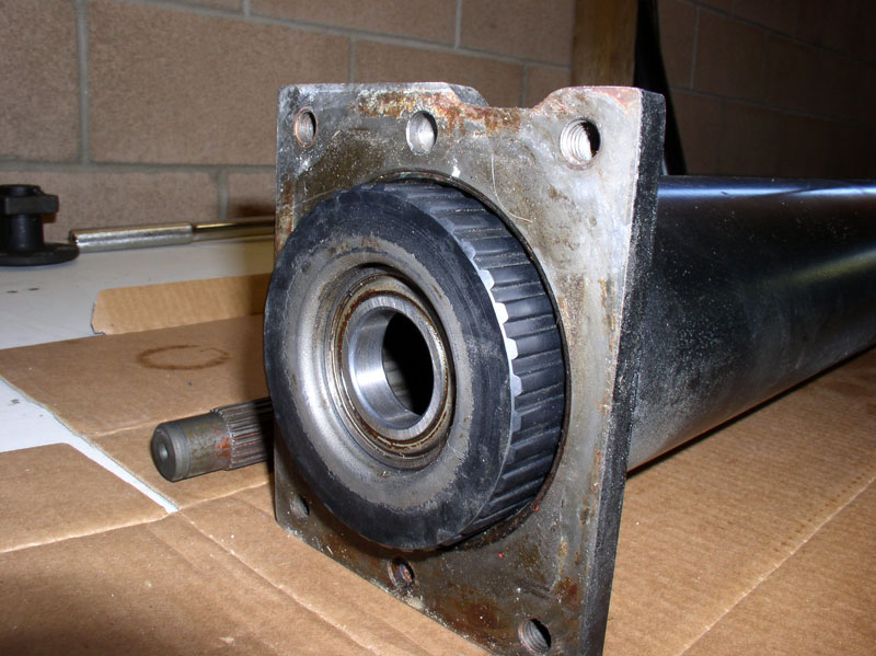
After installation, the forward bearing installed should look similar to the pic below. You are now ready to install the drive shaft.
Remove the threaded rod and confirm the proper spacing measurement. In this case, the forward bearing is 8 inches from the front of the TT.
After installation, the forward bearing installed should look similar to the pic below. You are now ready to install the drive shaft.
12-19-2010, 09:53 PM
#43
Rennlist Member
Thread Starter
Join Date: Sep 2007
Location: Ridgecrest, California
Posts: 1,363
Likes: 0
Received 143 Likes
on
28 Posts
CH12 INSTALLING DRIVE SHAFT
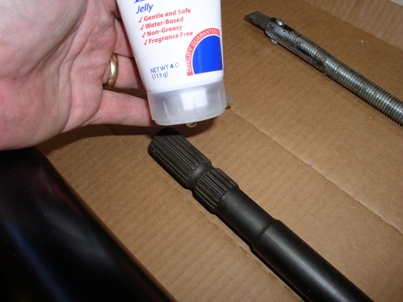
Next comes the best part of the whole job � using Personal Lubricant! Or as I commonly refer to it, �Personnel Lubricant.� Constantine supplies a tube of this water-based formula with his Super Bearings to ease installation of the drive shaft. Since it�s water-based, the water will eventually evaporate. However, use it very sparingly. In humid or damp environments, it can take a long time to dry.
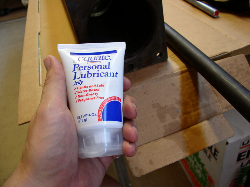
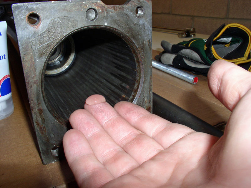
I applied the lubricant to both the Super Bearing rubber insert that contacts the drive shaft as well as the drive shaft. The amount shown on my finger in the picture below is actually too much and I would recommend just a dab about � or 1/3 the size shown for the bearings. Since the drive shaft will be installed from the front of the TT, lube up the front bearing first and wait to lube the rearward bearing just before the drive shaft is ready to go through the rear bearing. I moved quickly once I applied the lubricant so it wouldn�t dry out while I was installing the drive shaft. The lubricant can actually make it harder to install the drive shaft if it dries out and becomes sticky. If that happens during installation, consider spraying a small amount of water from a squirt bottle set on �stream� directed at the center of the bearing and drive shaft contact points.
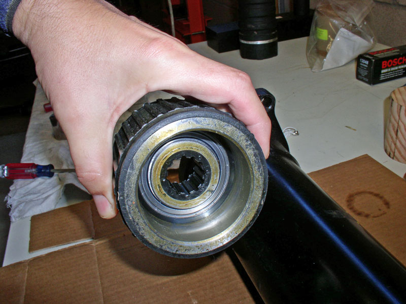
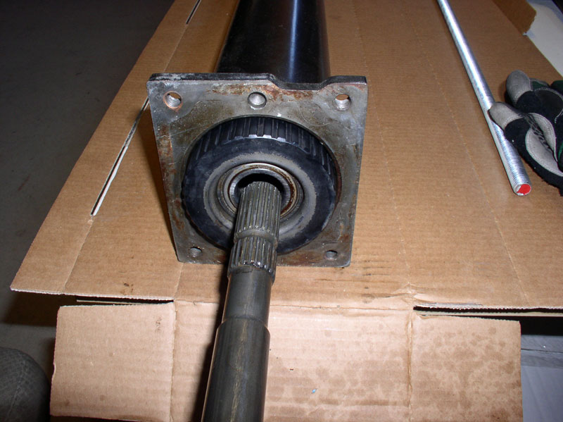
Constantine recommends using the OEM bearing and carrier to assist in the drive shaft installation. Remove the insert in the center of the bearing and leave the bearing installed in the carrier as shown below.
Gently press or tap the OEM carrier into position at the front of the TT as shown below. Do not force the carrier into the TT as it will be very difficult to extract the OEM carrier from the TT with the drive shaft running through it. Secure the OEM carrier in the TT only enough so it will stay put and can be pulled out by hand afterward. It is highly recommended to employ this method for guiding the drive shaft into the Super Bearings as it will minimize the risk of applying non-orthogonal lateral forces to the bearings when the drive shaft is pushed through the bearing inserts. Bottom line is you may damage the Super Bearings if the drive shaft is not perpendicular to the Super Bearing as it is pushed through. The method of using the OEM bearing carrier below will help keep the drive shaft straight and true while pushing through the Super Bearings.
Next, apply a small amount of �Personnel Lubricant� to the rearward end of the drive shaft. Apply to the splines as well as the smooth part of the drive shaft. Use sparingly. It is not necessary to apply lubricant to the entire drive shaft (only the rearward 2/3rds) as the front end of the drive shaft will not come into contact with the bearings.
Begin sliding the drive shaft into the TT. When I came up to the first bearing, I found it pretty easy to prod the bearing insert with the drive shaft until it felt like I found the center. I then pressed the drive shaft in by hand and it went through the first bearing inert fairly easy. I continued to push the drive shaft in by hand until it came up to the center bearing. Consider using an assistant to look through the end of the TT with a flashlight (through the rear bearing) to help guide you and let you know when the drive shaft is centered in the bearing insert. When it was centered, I then pushed the drive shaft through the center bearing with my hands. I continued to push the drive shaft through the first and second bearings until it reached the rear bearing. Pushing the drive shaft through two bearings is significantly more difficult than one bearing but it is doable by hand. At this point, the drive shaft should be lined up with the center of the rear bearing since the front bearing and center bearing are keeping the drive shaft aligned. Verify that drive shaft is aligned with the rear bearing insert and push the splines of the drive shaft through the rear bearing. Again, it is possible to do this by hand. I did not attempt to push the drive shaft the remaining distance by hand through all three bearings.
At this point, to push the drive shaft the remaining distance through the bearings, I found it easier to let gravity help with the task.
I placed a piece of scrap 2 X 6 lumber on the floor and set the forward end of the drive shaft on top of it as shown in the picture below.
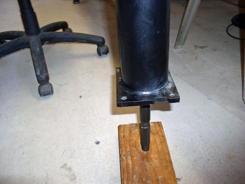
I placed another scrap piece of lumber on top of the TT as shown in the picture below. This was to provide a stop for the drive shaft and prevent it from being driven too far through the TT. I then lifted the TT and tapped the drive shaft down on the wood letting the weight of the TT and bearings help drive the shaft through the final rear bearing. This method proved to be fairly easy. I took my time and monitored the remaining distance the drive shaft needed to travel as I was �Tapping� the drive shaft through the TT in this manner. When the end of the drive shaft reached the scrap wood on top of the TT, I was done.
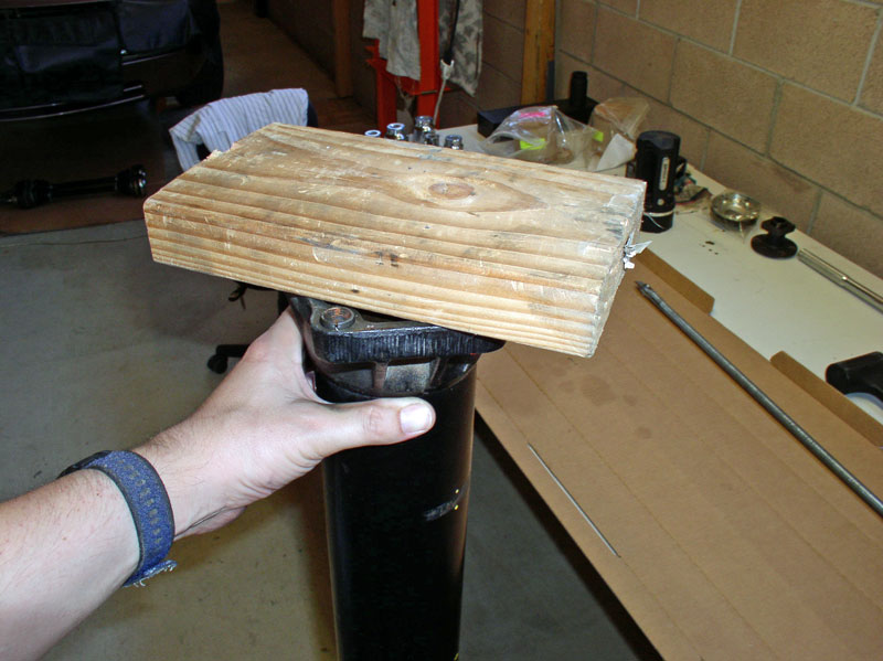
The manual states the drive shaft should protrude from the end of the TT by 1.5 to 2.0mm. Using the wood on top of the TT to stop the drive shaft worked great for me as it positioned the drive shaft almost perfectly. I assumed the 1.5 to 2.0mm measurement was to be taken from the rim of the round part of the TT as shown below. I found that with the wood stop resting on the end of the TT, it actually rested on the two locating pins (pictured below as well) and this provided enough additional clearance for the drive shaft to protrude approximately 2.0mm from the lip of the round part of the TT. To verify the measurement, I used a piece of wooden shim (available at most hardware stores) and using a micrometer, marked the edge of the shim at thickness of 1.5mm and again at thickness of 2.0mm as indicated by the green arrows in the picture below.
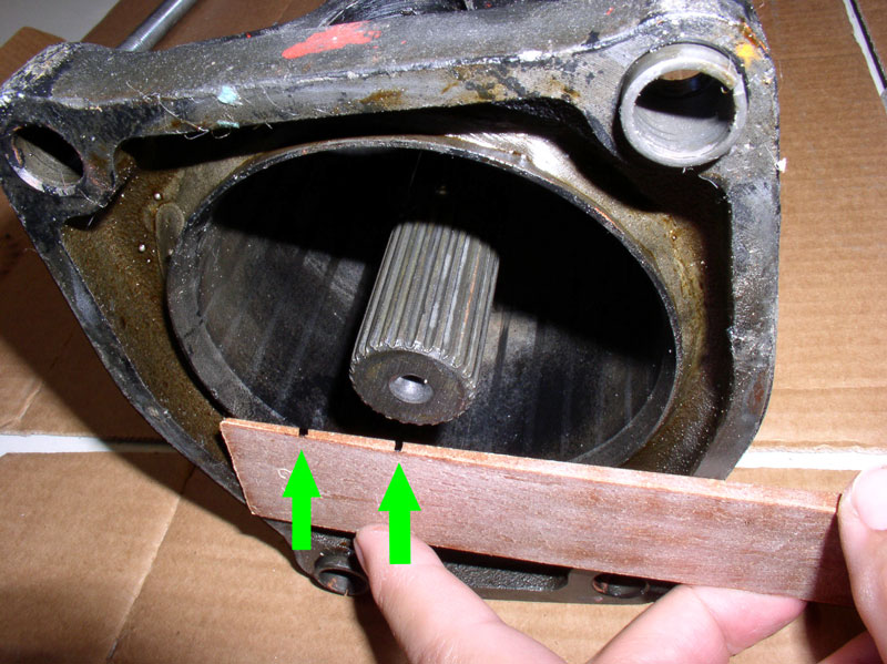
I placed the shim against the lip of the TT and as long as the end of the drive shaft was level with the shim at any point between the two marks, it would be within specification. Pictured below is a composite shim which worked OK but an actual wooden shim is longer and thinner at the end and would have made a better measuring tool as it would span the diameter of the TT lip easier. The next time I do this, I�ll use the wooden shim rather than the composite shim.
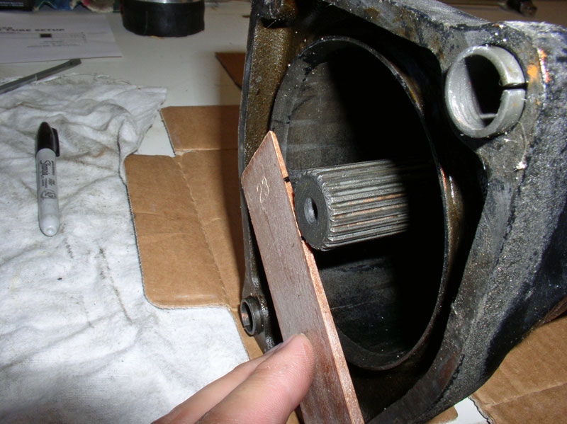
If the drive shaft is not within the required measurement, you can tap on the end of the drive shaft with a plastic dead blow hammer to move the shaft until it is in position.
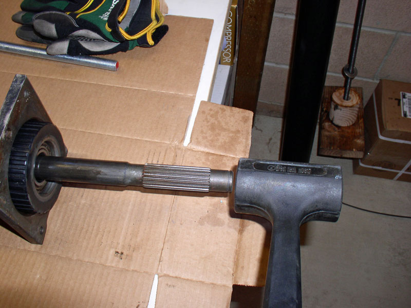
When the drive shaft is in position, remove the OEM bearing carrier from the front of the TT. At this point I tried spinning the drive shaft in both directions and listened carefully for any noises or roughness. It was smooth as silk and virtually silent. Ready to re-attach the TT to the transmission!
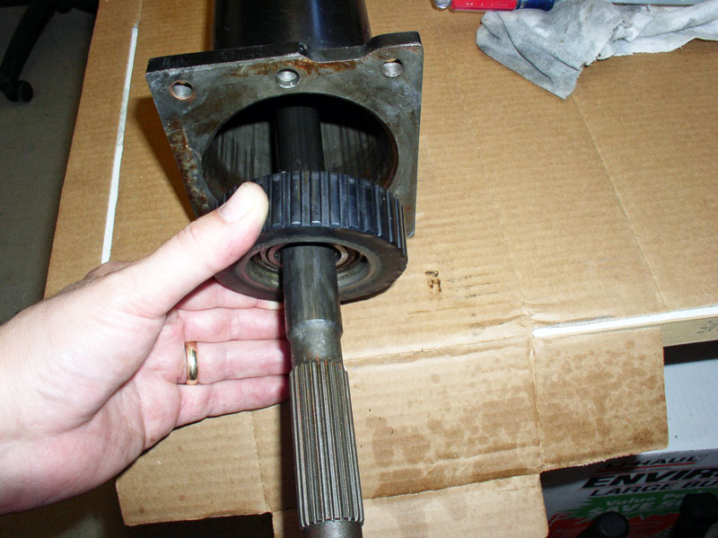
Next comes the best part of the whole job � using Personal Lubricant! Or as I commonly refer to it, �Personnel Lubricant.� Constantine supplies a tube of this water-based formula with his Super Bearings to ease installation of the drive shaft. Since it�s water-based, the water will eventually evaporate. However, use it very sparingly. In humid or damp environments, it can take a long time to dry.
I applied the lubricant to both the Super Bearing rubber insert that contacts the drive shaft as well as the drive shaft. The amount shown on my finger in the picture below is actually too much and I would recommend just a dab about � or 1/3 the size shown for the bearings. Since the drive shaft will be installed from the front of the TT, lube up the front bearing first and wait to lube the rearward bearing just before the drive shaft is ready to go through the rear bearing. I moved quickly once I applied the lubricant so it wouldn�t dry out while I was installing the drive shaft. The lubricant can actually make it harder to install the drive shaft if it dries out and becomes sticky. If that happens during installation, consider spraying a small amount of water from a squirt bottle set on �stream� directed at the center of the bearing and drive shaft contact points.
Constantine recommends using the OEM bearing and carrier to assist in the drive shaft installation. Remove the insert in the center of the bearing and leave the bearing installed in the carrier as shown below.
Gently press or tap the OEM carrier into position at the front of the TT as shown below. Do not force the carrier into the TT as it will be very difficult to extract the OEM carrier from the TT with the drive shaft running through it. Secure the OEM carrier in the TT only enough so it will stay put and can be pulled out by hand afterward. It is highly recommended to employ this method for guiding the drive shaft into the Super Bearings as it will minimize the risk of applying non-orthogonal lateral forces to the bearings when the drive shaft is pushed through the bearing inserts. Bottom line is you may damage the Super Bearings if the drive shaft is not perpendicular to the Super Bearing as it is pushed through. The method of using the OEM bearing carrier below will help keep the drive shaft straight and true while pushing through the Super Bearings.
Next, apply a small amount of �Personnel Lubricant� to the rearward end of the drive shaft. Apply to the splines as well as the smooth part of the drive shaft. Use sparingly. It is not necessary to apply lubricant to the entire drive shaft (only the rearward 2/3rds) as the front end of the drive shaft will not come into contact with the bearings.
Begin sliding the drive shaft into the TT. When I came up to the first bearing, I found it pretty easy to prod the bearing insert with the drive shaft until it felt like I found the center. I then pressed the drive shaft in by hand and it went through the first bearing inert fairly easy. I continued to push the drive shaft in by hand until it came up to the center bearing. Consider using an assistant to look through the end of the TT with a flashlight (through the rear bearing) to help guide you and let you know when the drive shaft is centered in the bearing insert. When it was centered, I then pushed the drive shaft through the center bearing with my hands. I continued to push the drive shaft through the first and second bearings until it reached the rear bearing. Pushing the drive shaft through two bearings is significantly more difficult than one bearing but it is doable by hand. At this point, the drive shaft should be lined up with the center of the rear bearing since the front bearing and center bearing are keeping the drive shaft aligned. Verify that drive shaft is aligned with the rear bearing insert and push the splines of the drive shaft through the rear bearing. Again, it is possible to do this by hand. I did not attempt to push the drive shaft the remaining distance by hand through all three bearings.
At this point, to push the drive shaft the remaining distance through the bearings, I found it easier to let gravity help with the task.
I placed a piece of scrap 2 X 6 lumber on the floor and set the forward end of the drive shaft on top of it as shown in the picture below.
I placed another scrap piece of lumber on top of the TT as shown in the picture below. This was to provide a stop for the drive shaft and prevent it from being driven too far through the TT. I then lifted the TT and tapped the drive shaft down on the wood letting the weight of the TT and bearings help drive the shaft through the final rear bearing. This method proved to be fairly easy. I took my time and monitored the remaining distance the drive shaft needed to travel as I was �Tapping� the drive shaft through the TT in this manner. When the end of the drive shaft reached the scrap wood on top of the TT, I was done.
The manual states the drive shaft should protrude from the end of the TT by 1.5 to 2.0mm. Using the wood on top of the TT to stop the drive shaft worked great for me as it positioned the drive shaft almost perfectly. I assumed the 1.5 to 2.0mm measurement was to be taken from the rim of the round part of the TT as shown below. I found that with the wood stop resting on the end of the TT, it actually rested on the two locating pins (pictured below as well) and this provided enough additional clearance for the drive shaft to protrude approximately 2.0mm from the lip of the round part of the TT. To verify the measurement, I used a piece of wooden shim (available at most hardware stores) and using a micrometer, marked the edge of the shim at thickness of 1.5mm and again at thickness of 2.0mm as indicated by the green arrows in the picture below.
I placed the shim against the lip of the TT and as long as the end of the drive shaft was level with the shim at any point between the two marks, it would be within specification. Pictured below is a composite shim which worked OK but an actual wooden shim is longer and thinner at the end and would have made a better measuring tool as it would span the diameter of the TT lip easier. The next time I do this, I�ll use the wooden shim rather than the composite shim.
If the drive shaft is not within the required measurement, you can tap on the end of the drive shaft with a plastic dead blow hammer to move the shaft until it is in position.
When the drive shaft is in position, remove the OEM bearing carrier from the front of the TT. At this point I tried spinning the drive shaft in both directions and listened carefully for any noises or roughness. It was smooth as silk and virtually silent. Ready to re-attach the TT to the transmission!
12-19-2010, 10:03 PM
#44
Rest in Peace
Rennlist Member
Rennlist Member
Join Date: May 2006
Location: Bird lover in Sharpsburg
Posts: 9,903
Likes: 0
Received 2 Likes
on
2 Posts
That is great Dwayne, I never knew that the SuperBearings were made to be serviced, not that i can imagine ever wearing one out.
the bearings are not only bigger, but have a higher speed and temp ratings than the originals.
I tell people that they sell them self, all they have to do is hold a stock one in one hand and a SuperBearing in the other, and they will know.
the bearings are not only bigger, but have a higher speed and temp ratings than the originals.
I tell people that they sell them self, all they have to do is hold a stock one in one hand and a SuperBearing in the other, and they will know.
12-19-2010, 10:19 PM
#45
Rennlist Member
Thread Starter
Join Date: Sep 2007
Location: Ridgecrest, California
Posts: 1,363
Likes: 0
Received 143 Likes
on
28 Posts
CH13 CONNECTING TT TO TRANSMISSION
Before mating the TT to the transmission, first install the drive shaft clamp onto the drive plate shaft. Line up the pinch bolt with the cutout on the drive plate shaft as indicated by the arrow in the picture below.
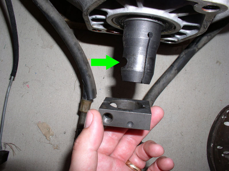
Before inserting the drive shaft splines into the rear flex plate shaft, I used brake cleaner and a wire brush to clean the splines so they were free of grease, dirt and debris. I used a floor jack to support the forward end of the TT while I aligned the rear splines of the drive shaft to the flex plate shaft coming out of the transmission. Using the floor jack made it easy to adjust the height of the TT so it was aligned with the transmission and allowed the drive shaft splines to be inserted into the flex plate shaft without binding.
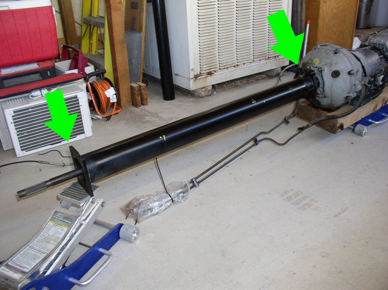
When the drive shaft is aligned, it should slide into the flex plate shaft without a lot of force. To fully insert the drive shaft and mate the TT to the TC casing, I provided a little support by slightly lifting the TT and very slightly moving side to side and up and down while pushing the TT toward the transmission. Notice there are locating pins on the end of the TT that will properly align the TT to the TC casing when the two are mated.
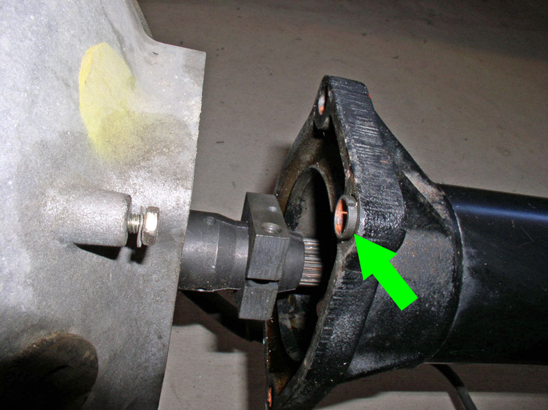
Press the TT in all the way until it is flush against the transmission TC housing as shown in the picture below.
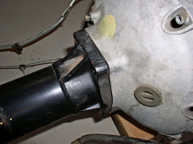
The TT-to-TC casing bolts were coated with copper anti-seize when I removed them so I applied a fresh coat before re-installing them.
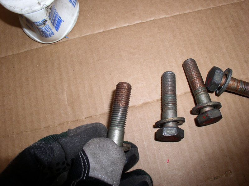
Insert all four bolts and hand tighten.
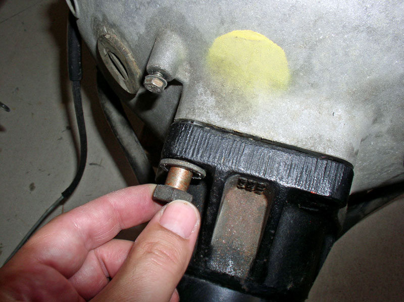
The Bolts take a 19mm socket. Torque the 4 bolts to 54-64Nm or approximately 45 ftlbs
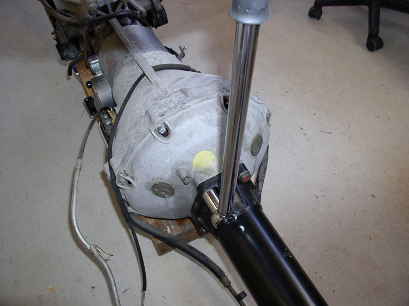
If the clamp has not moved, you should be able to insert the pinch bolt with no trouble. If it has moved, no problem. The clamp should move easily on the flex plate shaft so you can maneuver the clamp in place so the bolt can be inserted into the clamp.
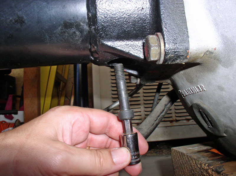
I snugged the pinch bolt with a socket but did not torque it to spec yet. The pinch bolt takes an 8mm Allen Head socket.
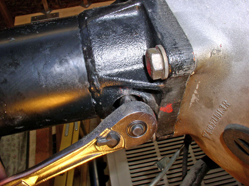
I prepared to secure the transmission fluid lines, Bowden cable, and vacuum line to the TT with the band clamps. The Bowden cable housing is attached to the TC housing using a 10mm bolt. I installed this bolt but left it loose as I would need to be able to maneuver the cable housing in order to position it correctly on the TT. Installing the bolt now (but not tightening all the way) will hold the Bowden cable housing in position while securing it to the TT.
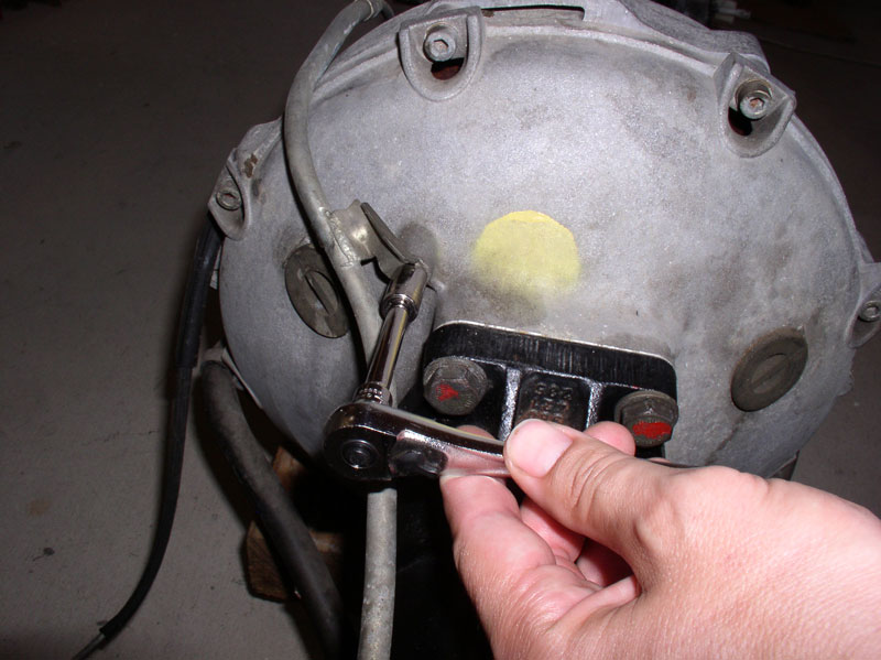
Next, I installed the band clamp at the rear of the TT and worked my way forward. Position the clamp in the same orientation as when it was removed. The tightening bolt on the clamp should be accessible from underneath the TT when it is installed it the car. The bends in the clamp will also help you to locate the fluid lines, Bowden cable housing and vacuum line in the clamp. Position the clamp on the TT between the marks previously made when removing the band clamps. I used yellow paint on this TT. Do not fully tighten the first clamp as you will need to slide the cables and lines around a little when installing the remaining clamps.
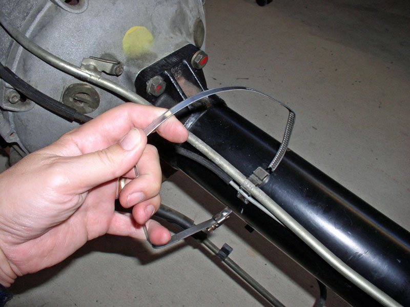
On this TT, the center clamp did not bind the Bowden cable or vacuum line � only the transmission fluid lines. Therefore, I clamped the lines as shown and positioned the clamp between the marks I had made on the TT earlier. Again, I did not fully tighten the clamp at this time.
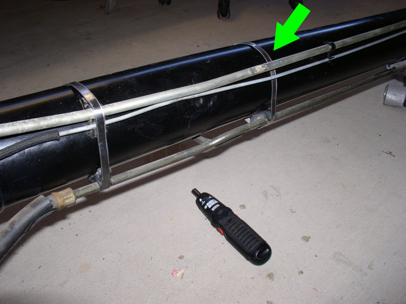
I installed the forward band clamp last. This band clamp clamped all the lines and hoses like the rear clamp.
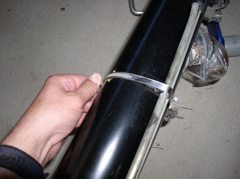
When the three clamps are installed (but not fully tightened), the TT should look something like the picture below. You may also be able to see the markings on the fluid cooler lines and Bowden cable housing where they came into contact with the band clamps. If so, line up the cooler lines and cable housing so they contact the band clamps in the same location.
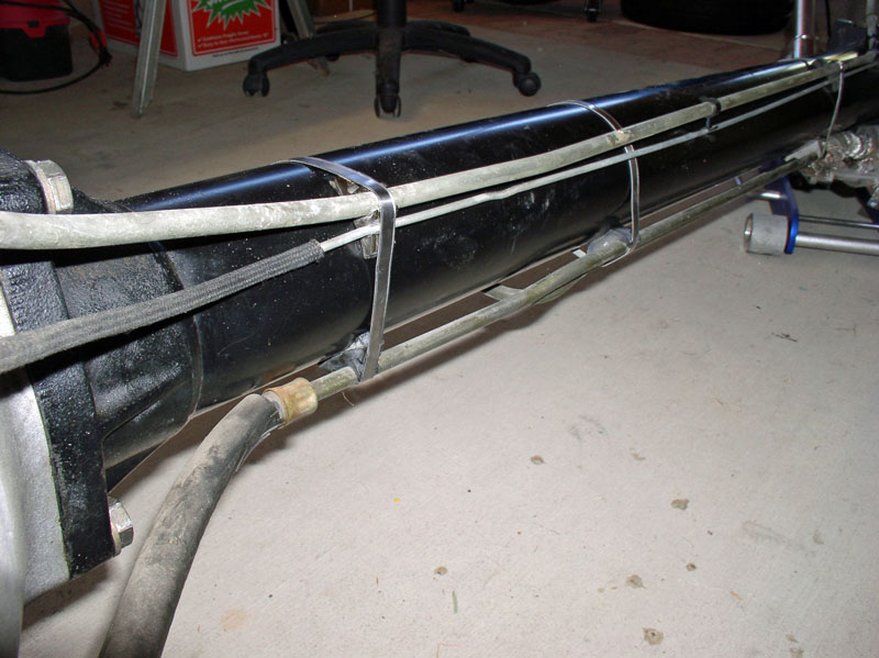
At this point, I fully tightened the Bowden cable-to-TC housing bolt with a 10mm socket as shown below.
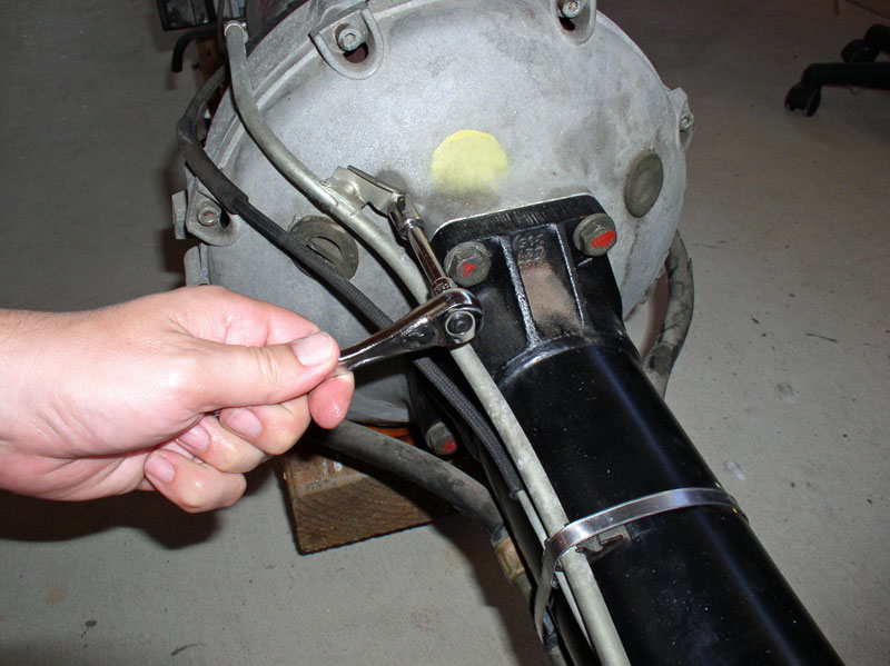
Continued....
Before mating the TT to the transmission, first install the drive shaft clamp onto the drive plate shaft. Line up the pinch bolt with the cutout on the drive plate shaft as indicated by the arrow in the picture below.
Before inserting the drive shaft splines into the rear flex plate shaft, I used brake cleaner and a wire brush to clean the splines so they were free of grease, dirt and debris. I used a floor jack to support the forward end of the TT while I aligned the rear splines of the drive shaft to the flex plate shaft coming out of the transmission. Using the floor jack made it easy to adjust the height of the TT so it was aligned with the transmission and allowed the drive shaft splines to be inserted into the flex plate shaft without binding.
When the drive shaft is aligned, it should slide into the flex plate shaft without a lot of force. To fully insert the drive shaft and mate the TT to the TC casing, I provided a little support by slightly lifting the TT and very slightly moving side to side and up and down while pushing the TT toward the transmission. Notice there are locating pins on the end of the TT that will properly align the TT to the TC casing when the two are mated.
Press the TT in all the way until it is flush against the transmission TC housing as shown in the picture below.
The TT-to-TC casing bolts were coated with copper anti-seize when I removed them so I applied a fresh coat before re-installing them.
Insert all four bolts and hand tighten.
The Bolts take a 19mm socket. Torque the 4 bolts to 54-64Nm or approximately 45 ftlbs
If the clamp has not moved, you should be able to insert the pinch bolt with no trouble. If it has moved, no problem. The clamp should move easily on the flex plate shaft so you can maneuver the clamp in place so the bolt can be inserted into the clamp.
I snugged the pinch bolt with a socket but did not torque it to spec yet. The pinch bolt takes an 8mm Allen Head socket.
I prepared to secure the transmission fluid lines, Bowden cable, and vacuum line to the TT with the band clamps. The Bowden cable housing is attached to the TC housing using a 10mm bolt. I installed this bolt but left it loose as I would need to be able to maneuver the cable housing in order to position it correctly on the TT. Installing the bolt now (but not tightening all the way) will hold the Bowden cable housing in position while securing it to the TT.
Next, I installed the band clamp at the rear of the TT and worked my way forward. Position the clamp in the same orientation as when it was removed. The tightening bolt on the clamp should be accessible from underneath the TT when it is installed it the car. The bends in the clamp will also help you to locate the fluid lines, Bowden cable housing and vacuum line in the clamp. Position the clamp on the TT between the marks previously made when removing the band clamps. I used yellow paint on this TT. Do not fully tighten the first clamp as you will need to slide the cables and lines around a little when installing the remaining clamps.
On this TT, the center clamp did not bind the Bowden cable or vacuum line � only the transmission fluid lines. Therefore, I clamped the lines as shown and positioned the clamp between the marks I had made on the TT earlier. Again, I did not fully tighten the clamp at this time.
I installed the forward band clamp last. This band clamp clamped all the lines and hoses like the rear clamp.
When the three clamps are installed (but not fully tightened), the TT should look something like the picture below. You may also be able to see the markings on the fluid cooler lines and Bowden cable housing where they came into contact with the band clamps. If so, line up the cooler lines and cable housing so they contact the band clamps in the same location.
At this point, I fully tightened the Bowden cable-to-TC housing bolt with a 10mm socket as shown below.
Continued....

