
'87 S4 Gremlins - No Power to Fuel Pump (SOLVED)
 08-13-2010, 05:58 PM
#1
Pro
Thread Starter
Join Date: Nov 2003
Location: Boston
Posts: 747
Likes: 0
Received 0 Likes
on
0 Posts
Hey guys, I've been sorting out the issues on my S4, have worked on it off and on all summer, haven't had much time to drive and enjoy her lately. Hoping to get back to semi-daily-driver status soon.
A bit of history: had been dealing with electrical intermittent no-start issues for a while. Cleaned all grounds, trouble-shooting with help from you all here. Ended up replacing the ignition switch. Did a bunch of wyit dash/pod stuff while I had it apart. Still resolving some issues in the dash too but got some of the things working, need to go back in and fix LED's still... Here's more detail on the dash and ignition stuff if at all interested.
Anyway after things were put back together the car would turn over strong but would not fire up. Determined no fuel. Tested back to fuel pump, which was not pumping fuel. The fuse and relay are healthy, and there's power to the hot side of relay. I ended up jumping the fuel pump directly off the cold side of the relay, so now the car starts right up. Running a bit rough, not sure if its due to it not being driven much this summer... these cars hate to sit unused. Or is it something more?
I'm wondering if it may have to do with EZK or LH... or if its just a wiring/connection problem. I need to study the wiring diagram some more, but I believe its after the relay, right? Would this cause the pump to not get the signal? Not sure if LH talks to fuel pumps or just injectors...
So I ran some spare wire from the fuel pump relay cold side, through the interior into the battery compartment, and out the little drain hole at the bottom. Wired it to the hot post on external fuel pump. See pics below. It fires right up like this, and I was able to drive it around the cape a bit with no other running issues. Could this be as simple as wiring going bad and need to be rewired? I'll go through and recheck connection but most of them are hard to see and get to. I didn't take the LH or EZK out during this dash project so that shouldn't be a factor, unless something was going bad coincidently. Anything else you guys can think of that would cause this?
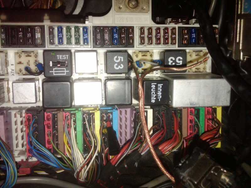
Fuel relay jump at panel
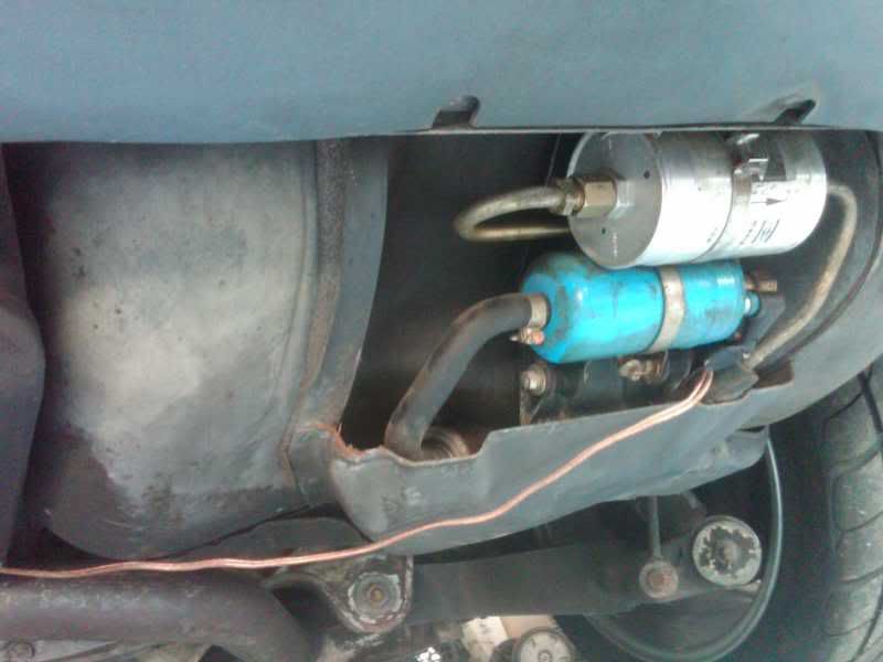
Fuel pump jump
Any advice much appreciated. I hate not driving this car!
A bit of history: had been dealing with electrical intermittent no-start issues for a while. Cleaned all grounds, trouble-shooting with help from you all here. Ended up replacing the ignition switch. Did a bunch of wyit dash/pod stuff while I had it apart. Still resolving some issues in the dash too but got some of the things working, need to go back in and fix LED's still... Here's more detail on the dash and ignition stuff if at all interested.
Anyway after things were put back together the car would turn over strong but would not fire up. Determined no fuel. Tested back to fuel pump, which was not pumping fuel. The fuse and relay are healthy, and there's power to the hot side of relay. I ended up jumping the fuel pump directly off the cold side of the relay, so now the car starts right up. Running a bit rough, not sure if its due to it not being driven much this summer... these cars hate to sit unused. Or is it something more?
I'm wondering if it may have to do with EZK or LH... or if its just a wiring/connection problem. I need to study the wiring diagram some more, but I believe its after the relay, right? Would this cause the pump to not get the signal? Not sure if LH talks to fuel pumps or just injectors...
So I ran some spare wire from the fuel pump relay cold side, through the interior into the battery compartment, and out the little drain hole at the bottom. Wired it to the hot post on external fuel pump. See pics below. It fires right up like this, and I was able to drive it around the cape a bit with no other running issues. Could this be as simple as wiring going bad and need to be rewired? I'll go through and recheck connection but most of them are hard to see and get to. I didn't take the LH or EZK out during this dash project so that shouldn't be a factor, unless something was going bad coincidently. Anything else you guys can think of that would cause this?
Fuel relay jump at panel
Fuel pump jump
Any advice much appreciated. I hate not driving this car!
Last edited by The_Remora; 08-16-2010 at 05:18 PM.
 08-13-2010, 06:05 PM
#2
Pro
Thread Starter
Join Date: Nov 2003
Location: Boston
Posts: 747
Likes: 0
Received 0 Likes
on
0 Posts
On a more positive note, the gauges look better than ever, the new 5-speed tach works great (5-speed conversion car, replaced the auto-tach while in there), the new Jager alum bezels came out nice. The speedo/odo STILL don't work after re-soldering and new odo gear... and LED's not working (they're not all in backwards)... so, some progress, but still a work-in-progress.
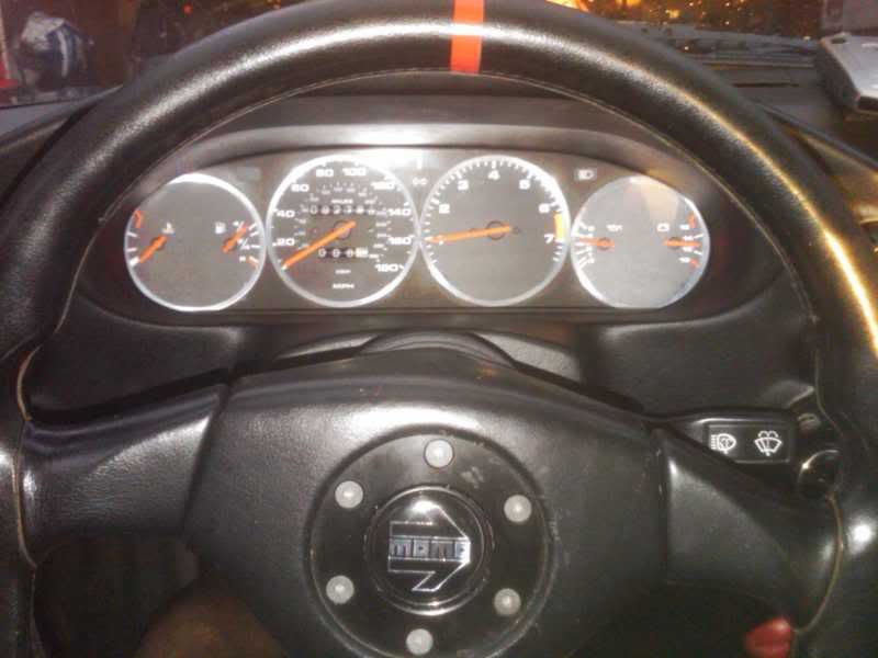
The Refurbished Gauge Cluster, with more work to be done...
The Refurbished Gauge Cluster, with more work to be done...
08-13-2010, 07:04 PM
#3
Rennlist Member
The fuel pump relay coil is energised by the LH ECU. One side of the relay coil is 12v, the LH ECU pulls the other side of the coil to ground to energise the coil and close the relay.
The LH will only pull the coil to ground when it receives RPM pulses from the EZK.
I would check that you have 12v on one side of the relay coil, when the engine is not running you will have 12v on the other side, but when engine starts to turn that will be pulled to ground. Check that any alarm/imobilser circuits are not also in series with the FP relay coil, this is a favourite place to connect the alarm.
08-13-2010, 09:06 PM
#4
Pro
Thread Starter
Join Date: Nov 2003
Location: Boston
Posts: 747
Likes: 0
Received 0 Likes
on
0 Posts
Thanks John, I will check these things. I was just looking a the wiring diagram and can see that the LH controls the relay. If it turns out that my LH or EZK is the culprit I will by buying one of your rebuilds from Roger or one of the other shops that carry them. Thx
08-13-2010, 10:44 PM
#5
Under the Lift
Lifetime Rennlist
Member
Lifetime Rennlist
Member
I'm trying to follow your description. Is it true that if you put a short jumper in the fuel pump relay socket from terminal 30 to 87 that the fuel pump still does not run; hence, you had to make that long jumper all the way back to the pump? If so, then this argues that the wiring from the relay output (terminal 87) out through U15 on the CE panel back to the pump is faulty. Further if by cold side you mean that you are running the wire from the intact relay terminal 87 back to the pump and the pump runs properly, that's evidence that the LH is fine and sending power to the FP relay.
08-13-2010, 10:57 PM
#6
Under the Lift
Lifetime Rennlist
Member
Lifetime Rennlist
Member
The speedo signal originates from an inductive pickup mounted on the backside of the differential. It should pulse a small voltage 8 times per revolution of the rear wheels. There is a two-pin connector for it in the spare tire well with two brown/red wires. It's possible that sender could be bad.
08-13-2010, 11:32 PM
#7
Pro
Thread Starter
Join Date: Nov 2003
Location: Boston
Posts: 747
Likes: 0
Received 0 Likes
on
0 Posts
Hi Bill, yes I think thats is the case. I say 'think' because I'm away from the car right now working up in Boston so can't verify the terminal numbers, but about to leave for Cape Cod in a few minutes where I have the car stored and will verify this tomorrow morning. I'm fairly sure I ended up running the wire from the relay output (terminal 87) straight back to the CE panel. I had tried jumping it back to the pump on the input side (30) and the car was able to start under that condition, so after testing the relay I ran it from output 87 and it started and ran like that too. So yes hopefully it is not the LH if thats in charge of throwing the relay switch. I'll go through this all tomorrow and verify. Thanks for working through this with me!
Trending Topics
08-13-2010, 11:50 PM
#8
Pro
Thread Starter
Join Date: Nov 2003
Location: Boston
Posts: 747
Likes: 0
Received 0 Likes
on
0 Posts
The speedo signal originates from an inductive pickup mounted on the backside of the differential. It should pulse a small voltage 8 times per revolution of the rear wheels. There is a two-pin connector for it in the spare tire well with two brown/red wires. It's possible that sender could be bad.
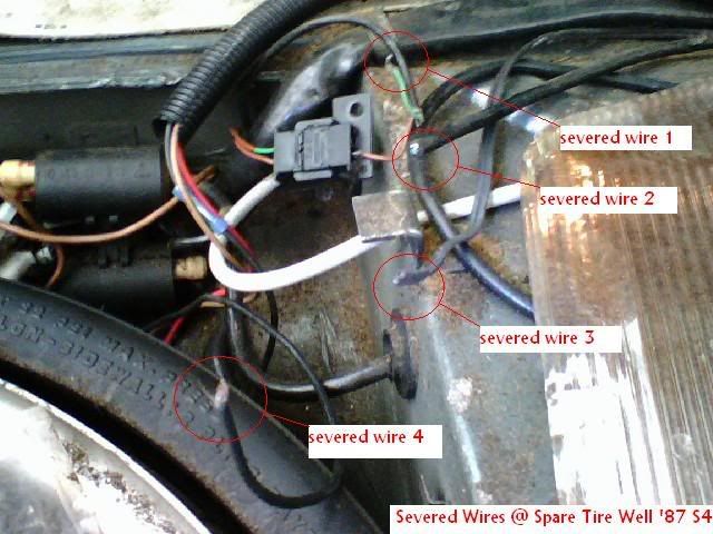
Here is a picture I took a bit ago of the wiring at the spare tire well in my car. I put the labels on to show all the exposed copper I found. I've since shrink-wrapped it. Is it possible to point out where that brown/red wires & two pin connector is in this pic, or at least where I should look in relation to this? Thanks
 08-14-2010, 12:40 AM
#9
Under the Lift
Lifetime Rennlist
Member
Lifetime Rennlist
Member
The black plastic connector is it. Reattach the green wire (severed wire one). The brown and green wires are the sender wires - it should go through a grommet down to the diff. Note that both wires on the other side of that plug are brown/red, although one wire has green paint on the first inch (so does mine). So, that's it.
Open up the other severed wires and report the colors. That black lamp cord (severed wire 3) looks like speaker wire, perhaps to a subwoofer that was removed.
Open up the other severed wires and report the colors. That black lamp cord (severed wire 3) looks like speaker wire, perhaps to a subwoofer that was removed.
 08-14-2010, 06:27 PM
#11
Pro
Thread Starter
Join Date: Nov 2003
Location: Boston
Posts: 747
Likes: 0
Received 0 Likes
on
0 Posts
I'm trying to follow your description. Is it true that if you put a short jumper in the fuel pump relay socket from terminal 30 to 87 that the fuel pump still does not run; hence, you had to make that long jumper all the way back to the pump? If so, then this argues that the wiring from the relay output (terminal 87) out through U15 on the CE panel back to the pump is faulty. Further if by cold side you mean that you are running the wire from the intact relay terminal 87 back to the pump and the pump runs properly, that's evidence that the LH is fine and sending power to the FP relay.
08-14-2010, 10:14 PM
#12
Pro
Thread Starter
Join Date: Nov 2003
Location: Boston
Posts: 747
Likes: 0
Received 0 Likes
on
0 Posts
The black plastic connector is it. Reattach the green wire (severed wire one). The brown and green wires are the sender wires - it should go through a grommet down to the diff. Note that both wires on the other side of that plug are brown/red, although one wire has green paint on the first inch (so does mine). So, that's it.
08-15-2010, 04:05 PM
#13
Pro
Thread Starter
Join Date: Nov 2003
Location: Boston
Posts: 747
Likes: 0
Received 0 Likes
on
0 Posts
So I found the reason the fuel pump was not working. After pulling the fuse panel to check the connections at fuel pump relay I found this shoddy speaker wire spliced into the the wire which runs from U15. It runs up under the dash to an old switch a PO/mechanic had installed as a way to cut off power to the fuel pump. The speaker wire runs back from the switch to the fuel pump fuse.
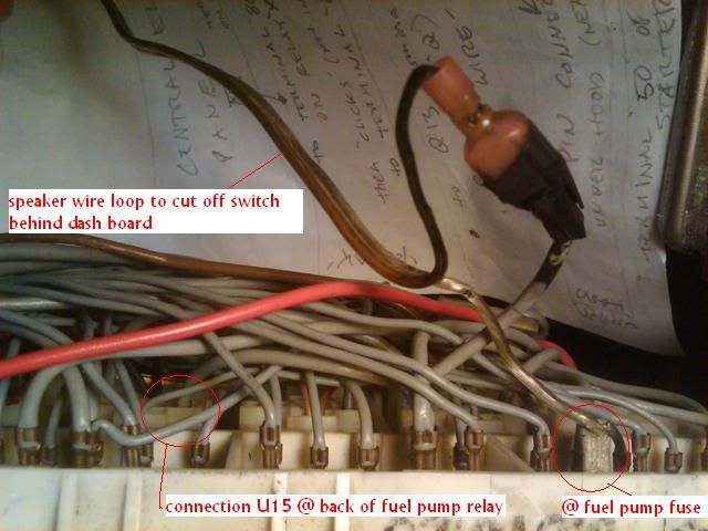
You can see that the speaker wire has blackened a bit near connection...it actually looks like it was burned up a bit, thats not tape or black wire insulation. I put some note paper behind the connection so it would stand out against dark background.
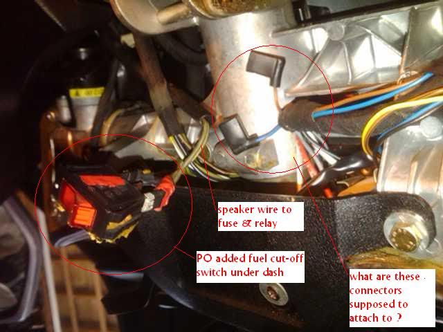
Here you can see the speaker wire running into this old switch. I found this when I was redoing the pod and thought it was probably for an old sub woofer or radar detector that was no longer installed, but it was actually this improvised anti-theft fuel pump cut off switch. The switch had been epoxied to the plastic trim and fell apart when I disassembled it to do the pod. I must have switched it to the 'off' position when working around it. So this makes way more sense as to why after redoing the pod the fuel pump stopped working. I figure I should remove all of this and rewire directly from U15 to the fuel pump fuse. This may help mitigate some of the draw on the battery that has been occuring which leaves me with chronic low/dead batteries.
Also, can anyone identify the two wires that are dangling there and where they are supposed to connect to? I took pics when doing the pod but didn't have any pics of where these were before I starting working around there... maybe my pod lights will work if i can figure out what connectors left off or attached wrong. Thanks! The project continues.
You can see that the speaker wire has blackened a bit near connection...it actually looks like it was burned up a bit, thats not tape or black wire insulation. I put some note paper behind the connection so it would stand out against dark background.
Here you can see the speaker wire running into this old switch. I found this when I was redoing the pod and thought it was probably for an old sub woofer or radar detector that was no longer installed, but it was actually this improvised anti-theft fuel pump cut off switch. The switch had been epoxied to the plastic trim and fell apart when I disassembled it to do the pod. I must have switched it to the 'off' position when working around it. So this makes way more sense as to why after redoing the pod the fuel pump stopped working. I figure I should remove all of this and rewire directly from U15 to the fuel pump fuse. This may help mitigate some of the draw on the battery that has been occuring which leaves me with chronic low/dead batteries.
Also, can anyone identify the two wires that are dangling there and where they are supposed to connect to? I took pics when doing the pod but didn't have any pics of where these were before I starting working around there... maybe my pod lights will work if i can figure out what connectors left off or attached wrong. Thanks! The project continues.
08-16-2010, 07:53 PM
#14
Under the Lift
Lifetime Rennlist
Member
Lifetime Rennlist
Member
I think the blue and brown wires are for a speed warning buzzer not installed on US cars.
The odo issue is probably mechanical. Even if you replaced the odo gear it still may have looseness between the number wheels so they are not engaging. A small, thin washer used as a shim on the end of the shaft can tighten it up.
The odo issue is probably mechanical. Even if you replaced the odo gear it still may have looseness between the number wheels so they are not engaging. A small, thin washer used as a shim on the end of the shaft can tighten it up.
