When you click on links to various merchants on this site and make a purchase, this can result in this site earning a commission. Affiliate programs and affiliations include, but are not limited to, the eBay Partner Network.
I don't know what to say, Rob! Clamp-OCD has an ICD-9-CM code now? ;-)
Seriously, though, have to admire how systematically you're approaching this 928 thing.
For the turbo car, the clamping problem on the low pressure side of the compressor is mainly related to the size and fit, as there's no room and the clamps can't rub anything. On the high pressure side, there's the thermal expansion issue as the temperature fluctuates considerably, and the clamps can't cut into the silicone connector. And of course there's not room.
On the low pressure side, the main things that those clamps have to do are maintaining location and hold down the heat shields without cutting into the silicone. On the high pressure side, there's the pressure force as well. The high pressure side is 2.5"-2.75" by the way...
I don't know what to say, Rob! Clamp-OCD has an ICD-9-CM code now? ;-)
Yes, ICD-10 is F60.5, But it gets worse:
Turns out Gemi has a 50-70 mm clamp that might work for 2.5-2.75" applications, looks like they're narrower than the ABA you showed above, if that would help with the space issue (?).
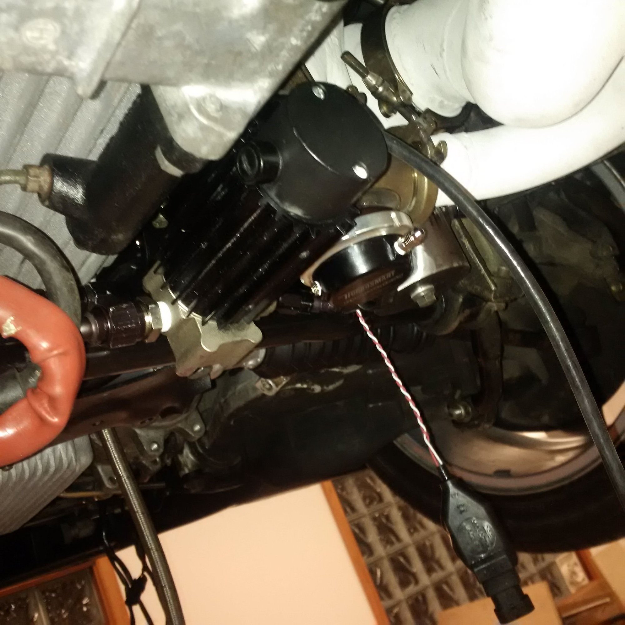
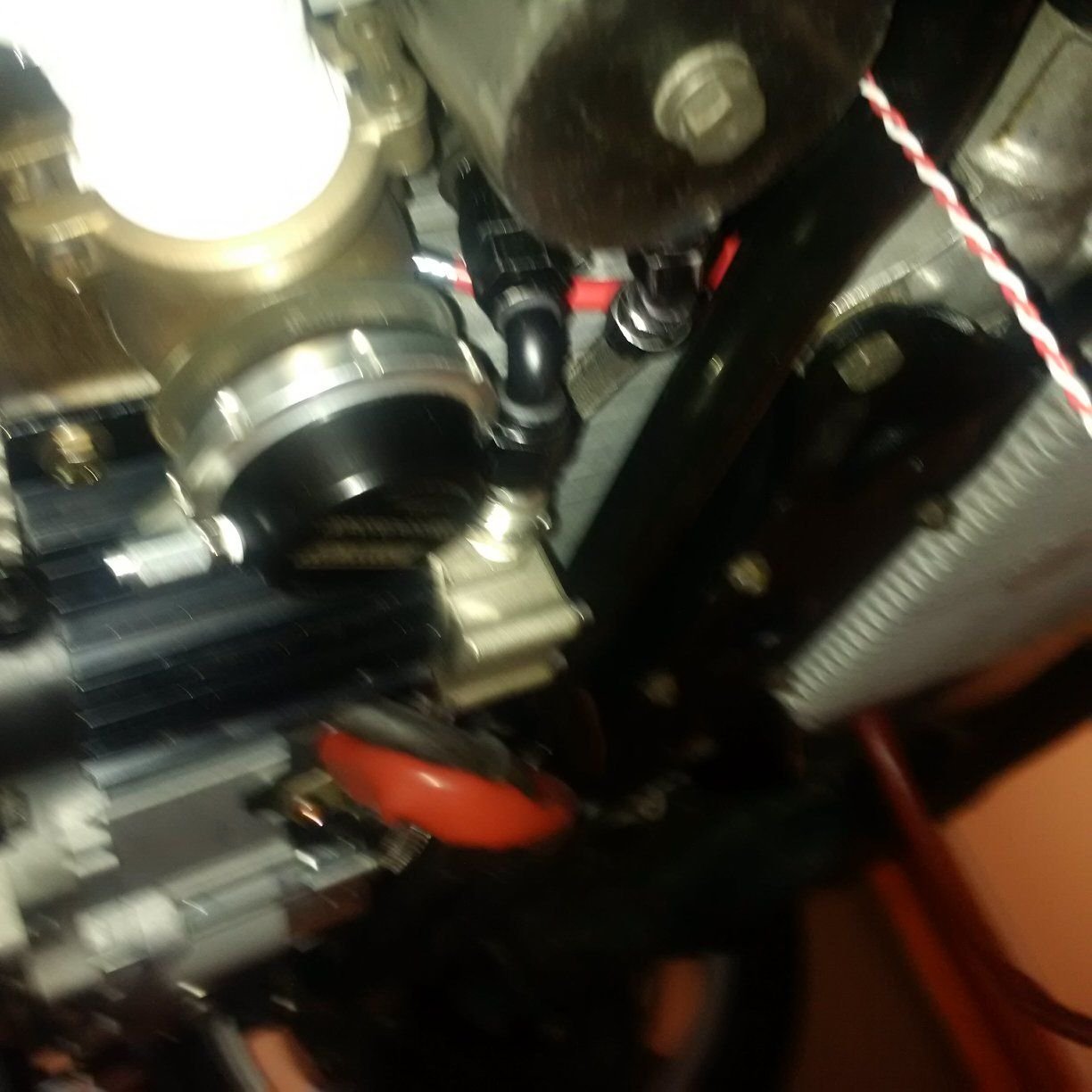
The new oil pump bracket is in. This one fits clean with an engine that has an oil pan spacer and a mini starter. The main thing is running the oil lines.
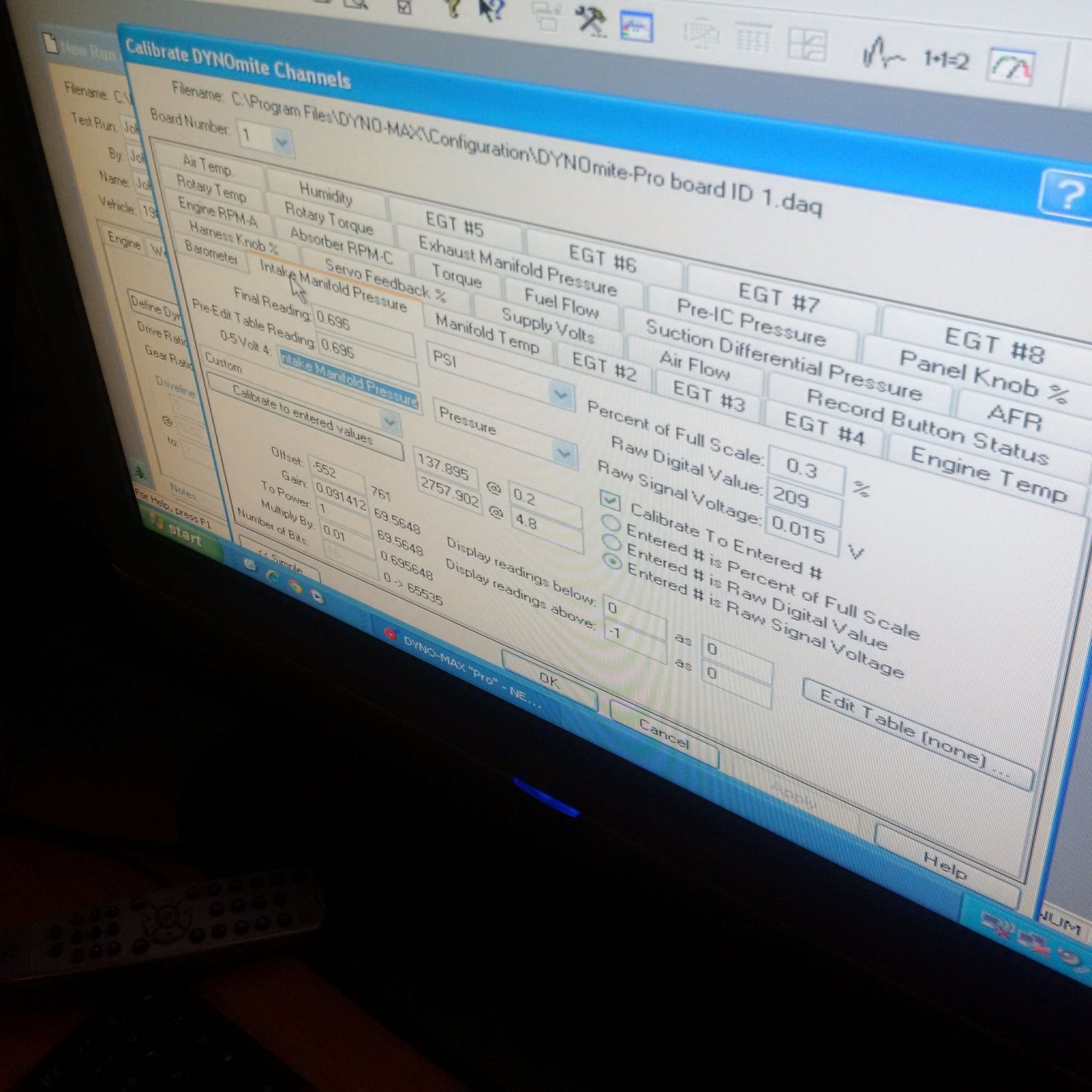
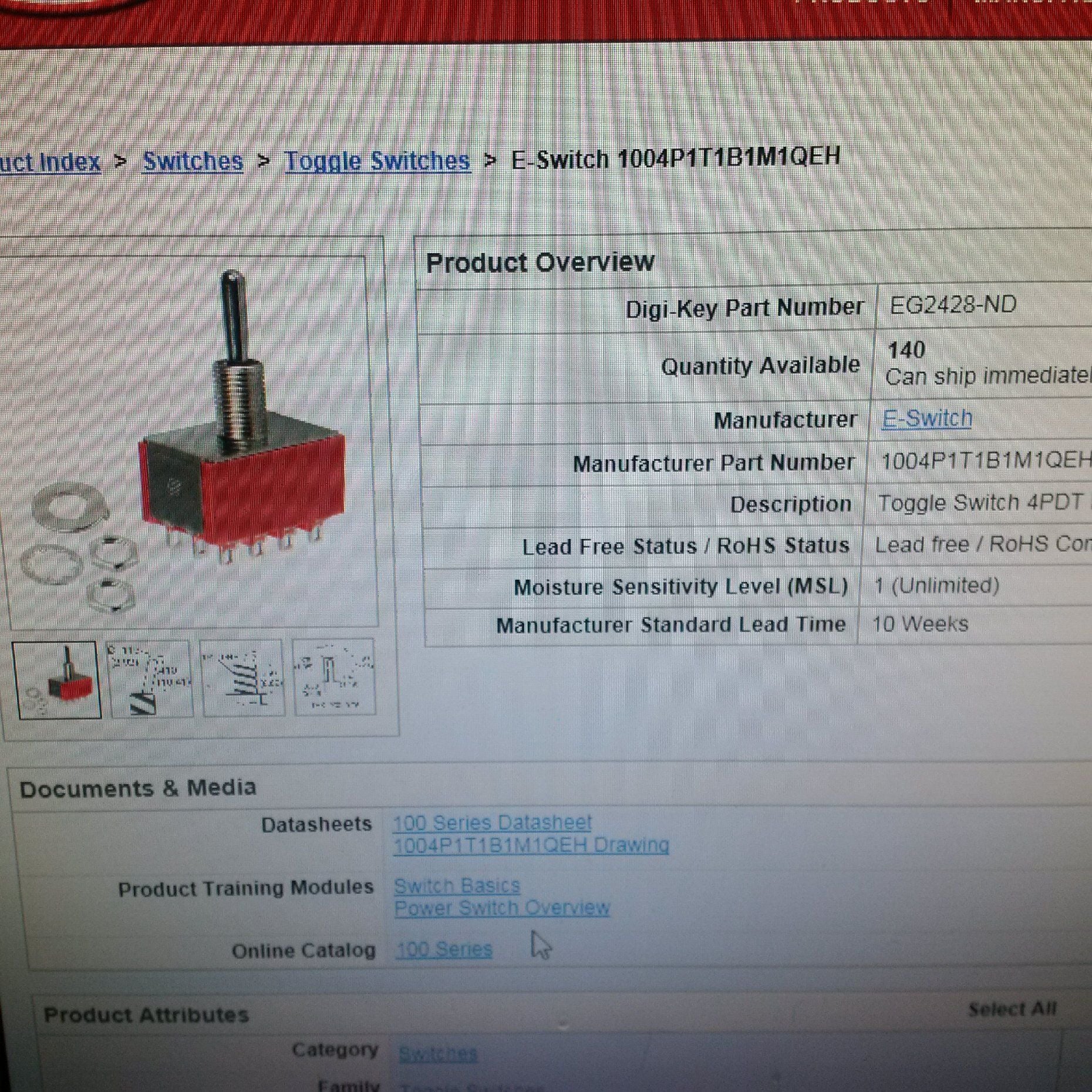
The sensors are being set up on the motor, dyno being set up for the sensors, and the turbo speed gauge will now have a toggle switch to show each side reading, etc.
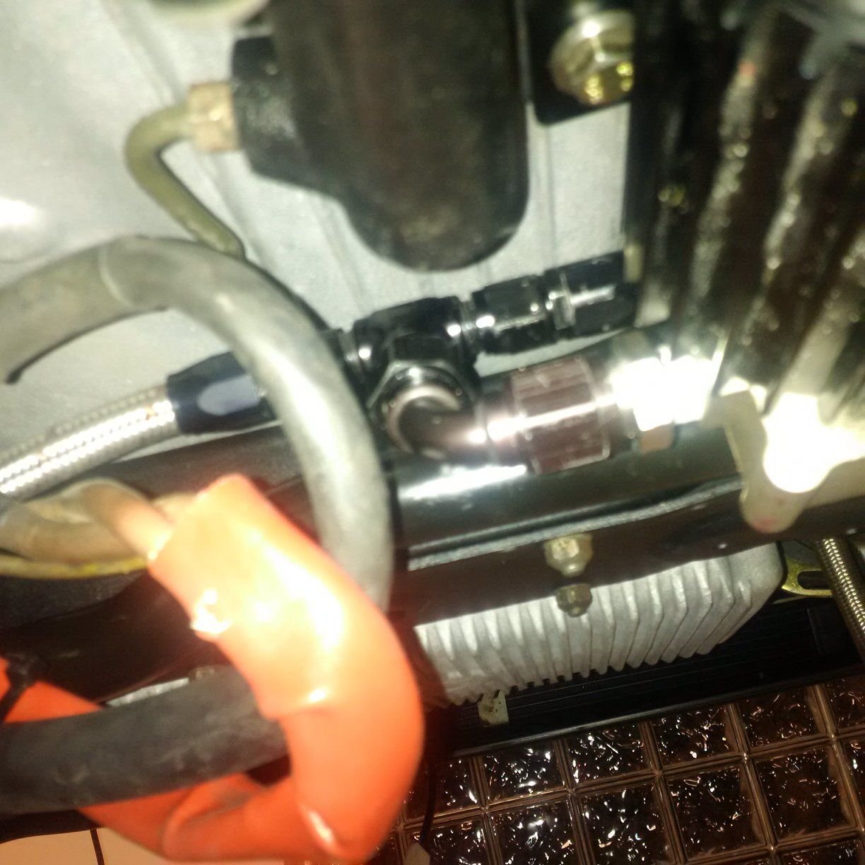
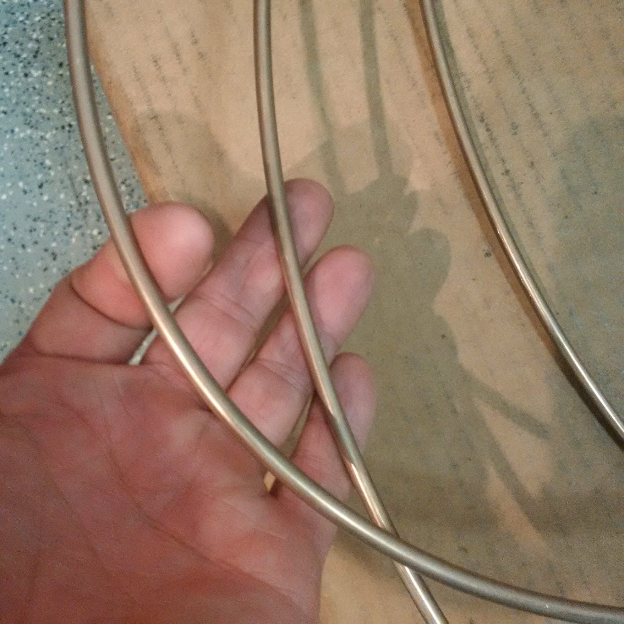
Here's how the new lines are run. The routing has to be a little different because of the oil pan spacer:
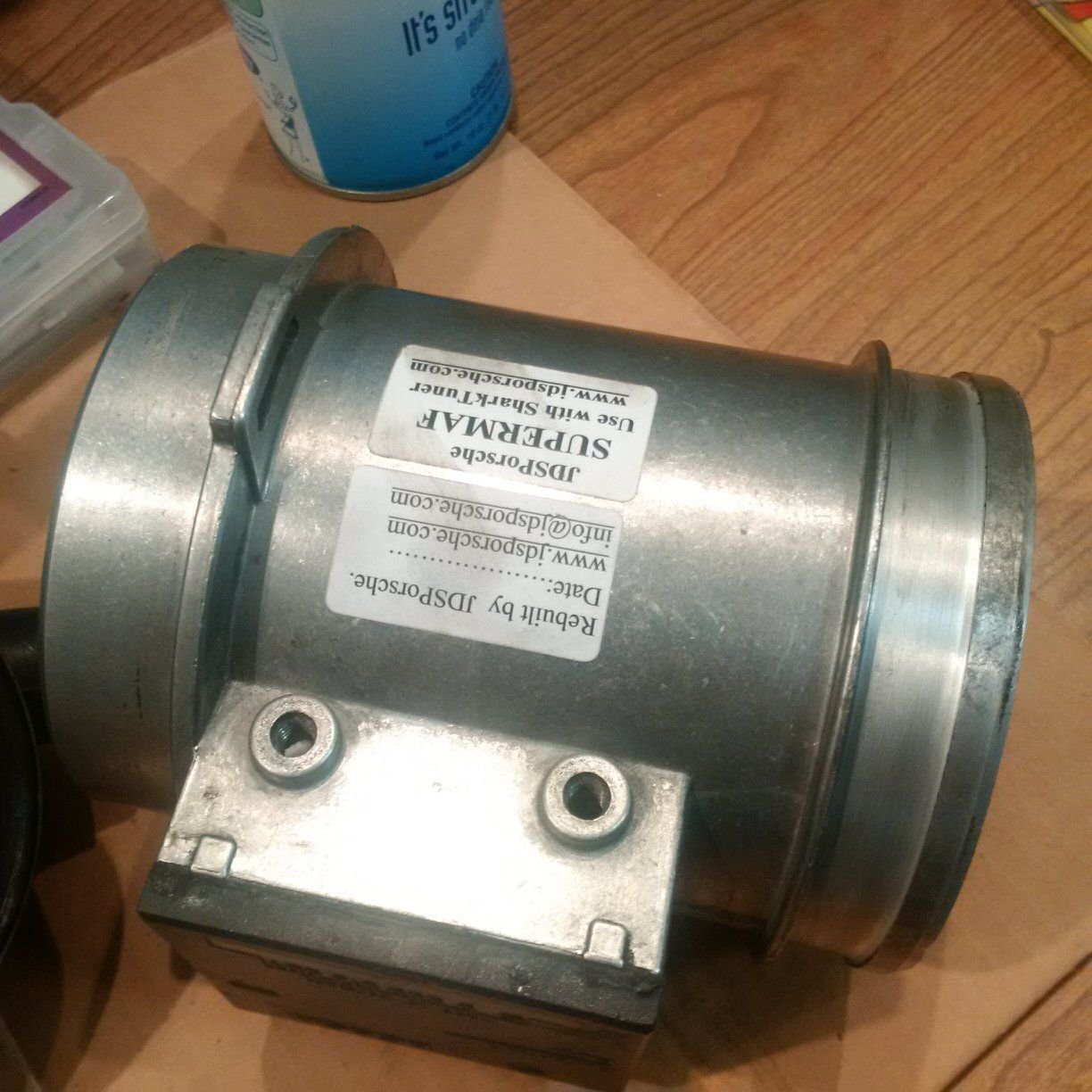
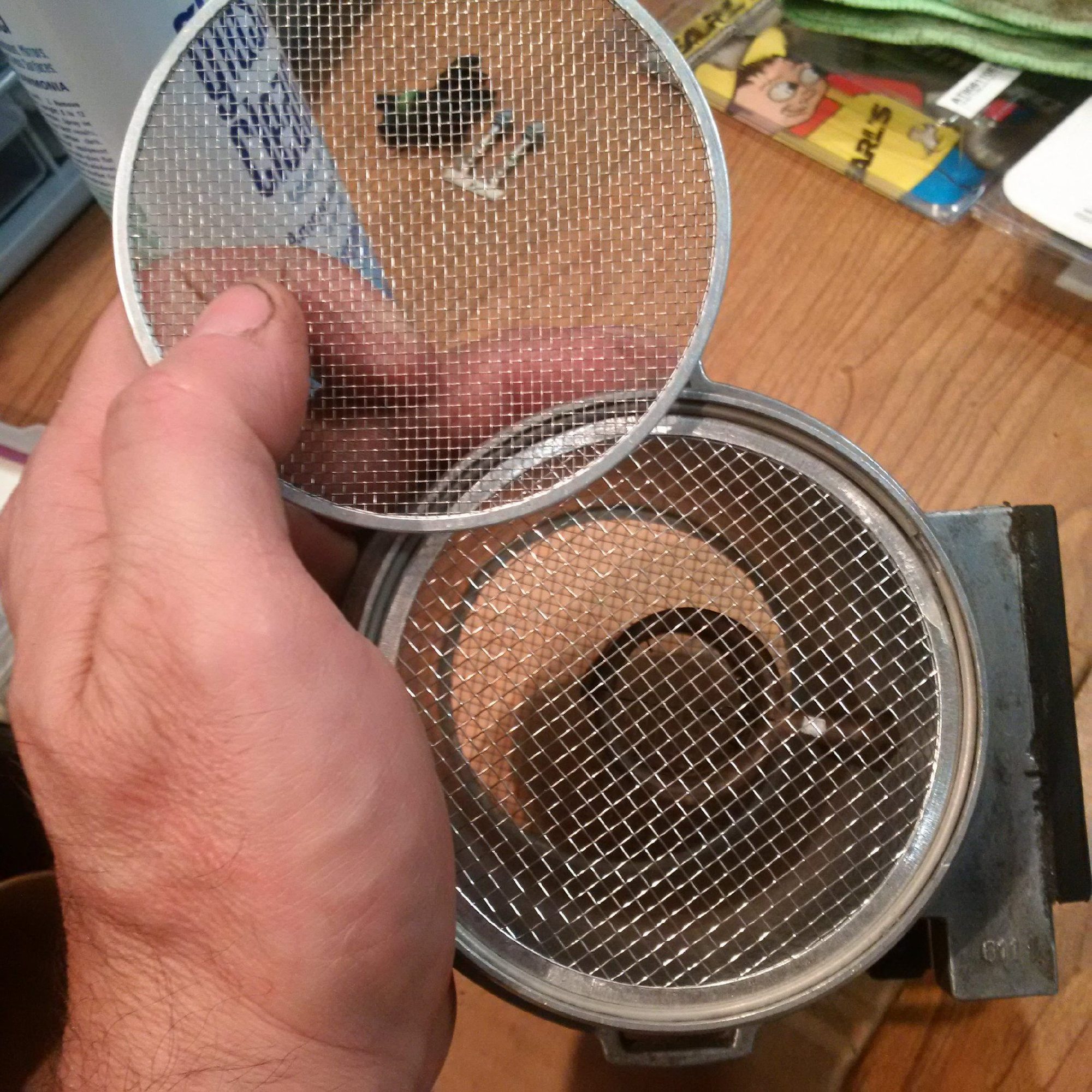
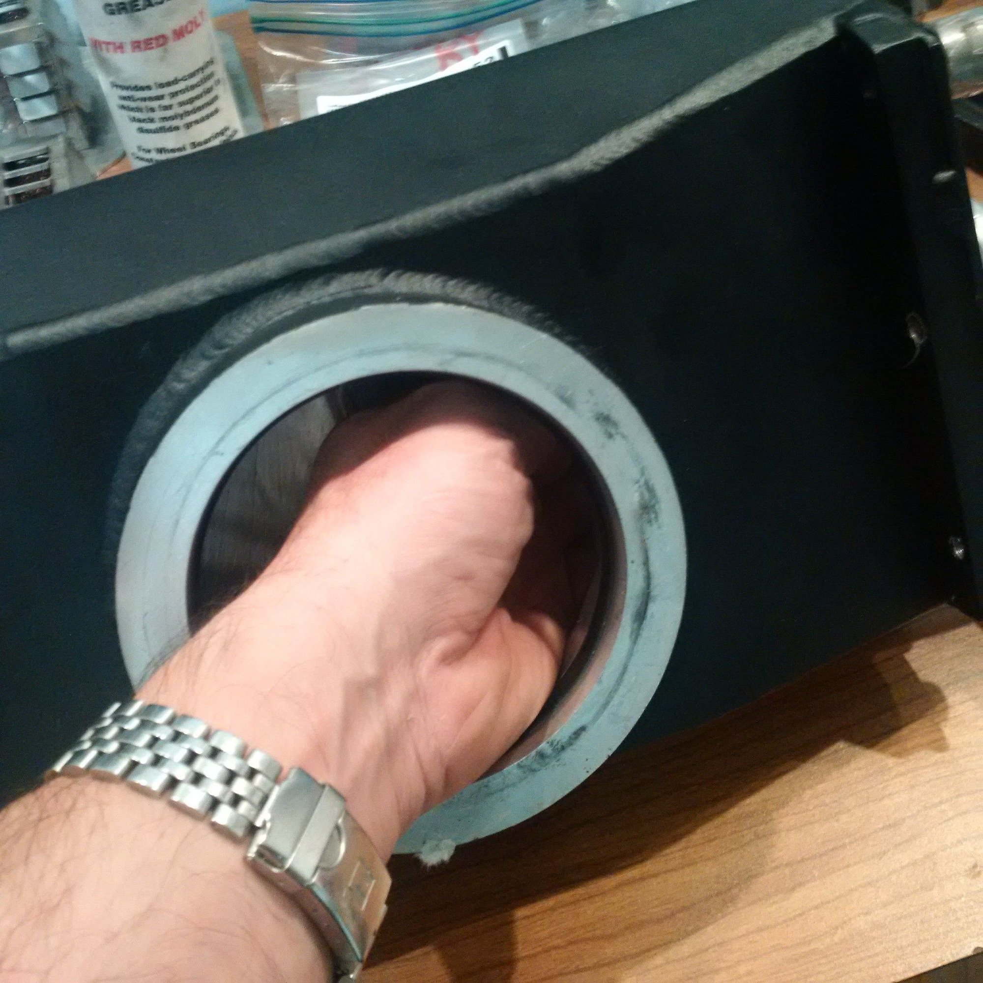
The basic scheme is the same as before. There are two cylinder shaped sumps, one per turbo. Those sumps serve two functions. First, they allow the air to separate from oil into larger bubbles. The turbo oil drain outlet has a fair bit of foam. Depending on conditions, oil and air move up/down and from/to the BMW air oil separator drain line. The drain line has to be large for that reason, and will not have a check valve. Under most (possibly all) conditions, the oil pump capacity is large enough that it will pull, in net, air out of the BMW air-oil separators, but the system will operate even if the pump capacity is below that threshold. Just some defensive design there. Second, the sumps allow oil to accumulate in one of the sumps in extreme cornering.
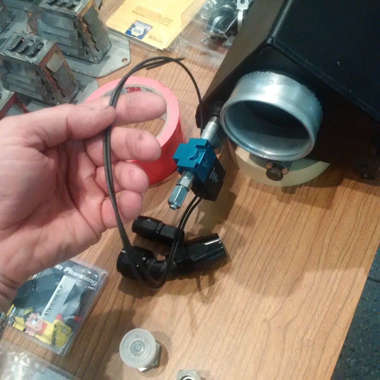
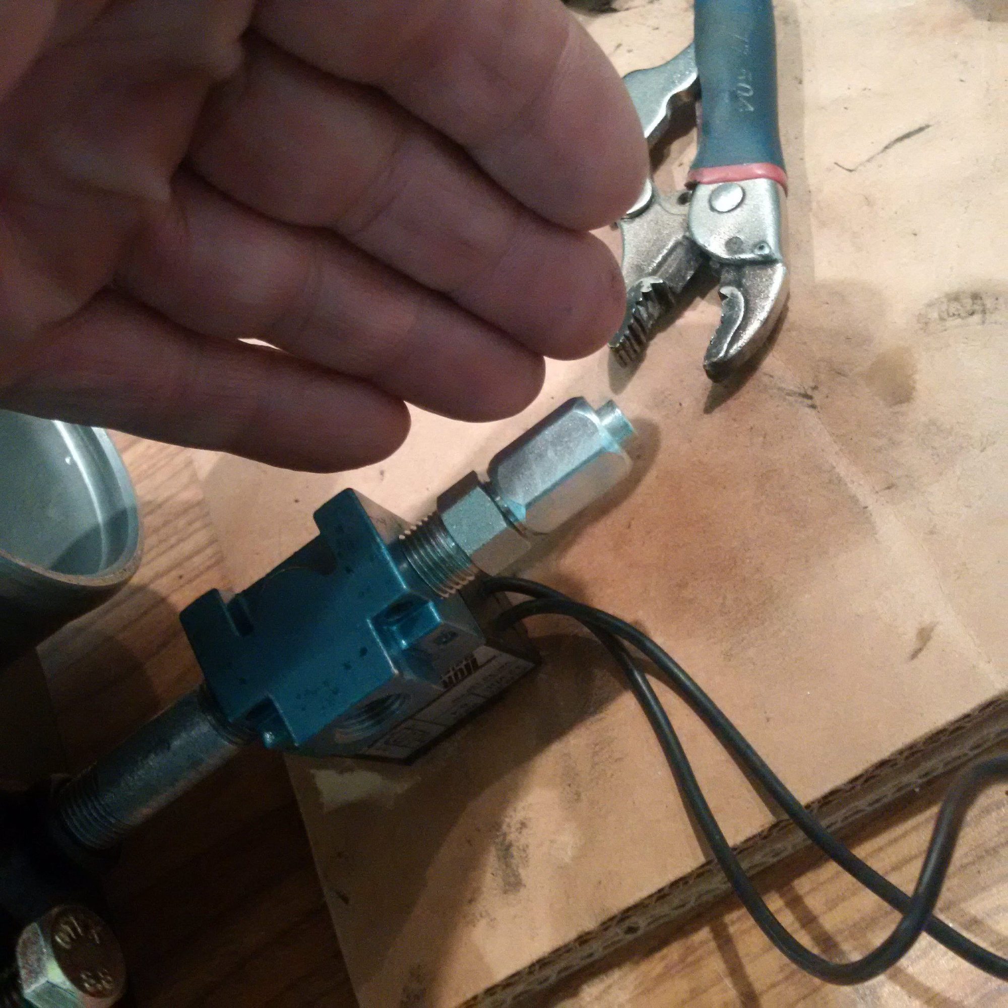
This setup will have two solenoid valves. The solenoid valve will send pressure to closing side of the wastegate diaphragm. This will allow us to control the boost at high intake and exhaust manifold pressure levels. The lines are flared hard lines, no temperature issues ever:
(iPhone user interface for posts that have images is completely useless on this site.)
The intake manifold pressure is connected to the opening side of the wastegate diaphragm as in the simple system without any electrical valves. The solenoid valve is plumbed on the closing side. It pulses pressurized air from the plenum box into that opposite side of the diaphragm. If the valve provides full open, that is, the full pressure to the opposite side of the diaphragm, then the forces on the both sides of the diaphragm cancel and the only net on the gate are the exhaust back pressure trying to open it and the spring holding it closed.
The EB2 controller is similar to the standard PID-controller, so although the tuning parameters will likely have to be changed for this new "passive-aggressive" gate settings, I don't anticipate any long-term control algorithm problems there.
8 temp, 5 pressure and 1 delta-P transducer? Whole lotta data, wow. The pressure drop across the intercoolers is assumed to be the same side-to-side? Why not delta-P and the two temps on the same intercooler?

 10-21-2016, 12:41 PM