When you click on links to various merchants on this site and make a purchase, this can result in this site earning a commission. Affiliate programs and affiliations include, but are not limited to, the eBay Partner Network.
A couple of words about this new engine. It's a combination of proven modifications and my cockamamie theories.
The proven out things are those that have been used in Dennis Kao's engine and George Suennen's engine. Both are 5.0L weight class 928 world beaters, the big fish in the tiny 928 pool.
The cockamamie theories are mostly all mine. Examples include:
Having the heads ported by a "guru." Looking back, all that was at best unnecessary. With hindsight I appreciate the unintentional comedy. The valves might be worse than the stock valves, all I know...
Testing some very low spring load valve springs. There's a proven spring solution in S2/968 springs. Not only am I trying something unproven but setting those springs to what I am guessing is the minimum required load, in a boosted engine of all things?! What am I thinking?
I decided to have the pistons dished. Now, I am actually pretty confident in that since the design and implementation were not mine. But I could have just stayed at 9.4:1 static compression ratio shift the torque curve to the left with the cams. But more is never enough and too much is just right...
Lets just say that at minimum, we'll learn new things from this new motor! ;-)
So what's the point of this swap? The main point from the power production perspective are Elgin 65-6 cams and lower static compression ratio of about 8.6:1. Both those lower the effective compression ratio, allowing more boost. The bigger cams will move the torque curve to the right, allowing making more power at the knock limit (which is more related to torque). There are a lot of other things there, these are just the points that are most relevant for power production.
Why has swapping this engine in taken so long? We've been chipping away at the bottle necks in the turbo system that was originally designed be comfortably sized for 600 crank hp. At about 800 crank hp, multiple points in John's turbo system hit the wall -- a sign of excellent design, by the way. You want everything to run into a wall at about the same percentage outside the design target. It made no sense to put in the low compression, bigger cam engine when we're running into the compressor mass flow limit or overwhelming the compressor inlet capacity.
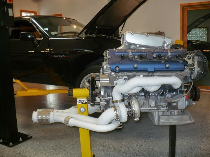
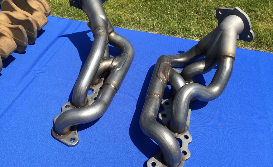
This is what the engine looks like with the old exhaust manifolds:
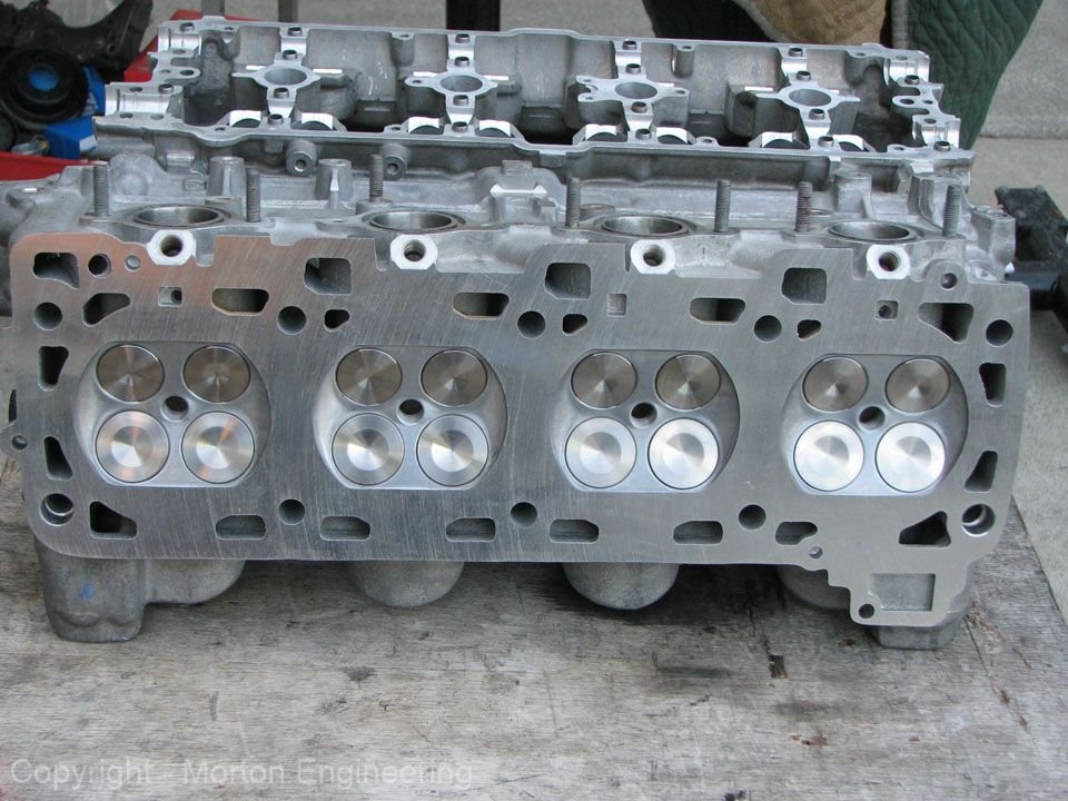
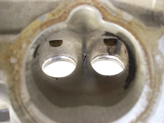
Here are the heads. Jim snapped the photo, but he's got nothing to do with the porting job. If anyone ever charges him with porting these heads, I'll refer them to Biggy Smalls:
At my arraignment, note for the plaintiff
Your daughter's tied up in a Brooklyn basement
Face it, not guilty, that's how I stay filthy
Richer than Richie, till you n****s come and get me
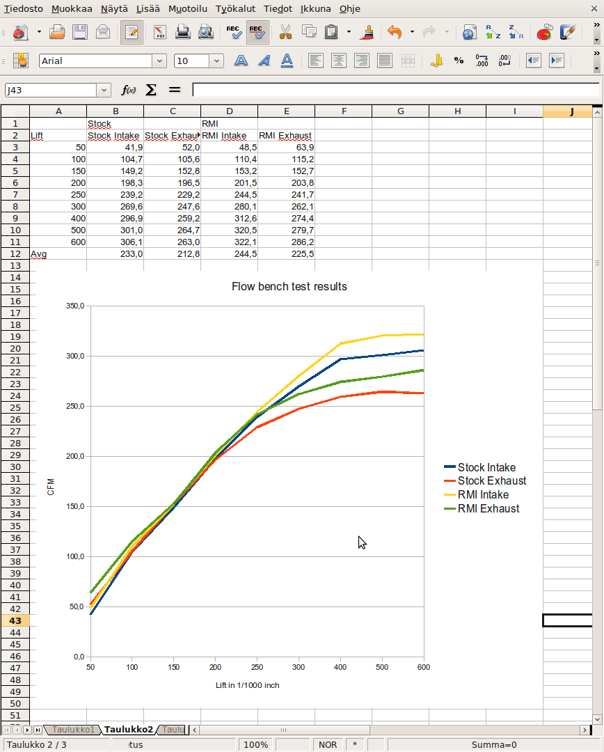
This is what they flow:
These heads were ported before I knew for what I should have asked. In any case, I asked for good low lift flow, assuming that I'd be running stock cams.
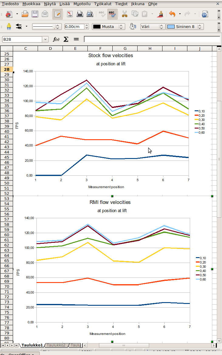
I think I've posted this on another thread before, but here it's again. This is how the local velocity is more even in the ported heads:
Now, these data are from the head porter and not independently verified. Still, with that grain of salt, I think it's probably the case that the low lift flow with these heads is at least as good as stock heads and the high lift flow is better. Also, based on what I know now, the velocity info is credible.
In terms of risk factors for the plans, there are a couple. Apart from the above experimental stuff, the main risk factor is probably the following.
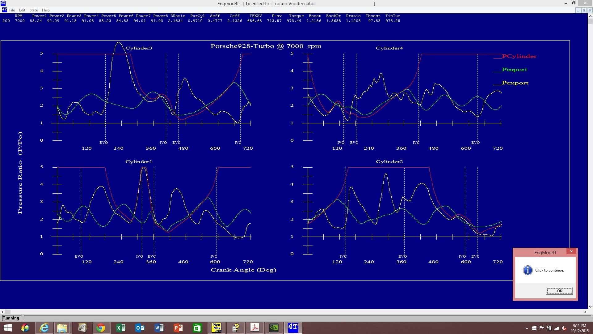
Based on our modeling efforts, cylinder #1 is likely to have a low knock limit at high rpms and boost levels. The short-runner #1 overtakes the long-runner cylinders as the most knock-prone cylinder at about 5700 rpm. At 6500 rpm, the predicted maximum temperature of unburnt mixture is about 20C higher than the second worst cylinder, with all the rest of the cylinders bunched up within a 20C range. At 7000 rpm, we'll likely be in trouble.
Why is this? It's all about the exhaust interference and the physical distance between the cylinders #1 and #3. Cylinder #3 blows a big exhaust blowdown pulse which peaks at the time when the cylinder #1 intake valve opens during the overlap. That has the potential of blowing the exhaust gas up the intake port, quite the opposite of what's supposed to happen during the overlap. This is not unique to the 928 turbo system, all single-scroll twin turbo 90-degree cross-plane V8s with turbos on the outside fed from a single bank have the same problem.
You may notice that the simulations have a problem on the passenger side and not much of a problem on the driver side. The reason why the high-rpm 90-degree blowdown interference from #3 really hurts #1, but the 90-degree blowdown interference from #5 doesn't really hurt #6 is the following. The physical distance between #1 and #3 is much greater than #5 and #6. Consequently, at 7000 rpm, the pulse from #3 takes long enough time that #1 is already at the overlap. In contrast, the pulse from #5 arrives at #6 earlier when #6 is still in exhaust pumping stage. So the end result is that #3 runs great blowing its load into #1 during #1's overlap, #1 gets killed, while #5 and #6 both suffer the higher pumping losses from trying to push the exhaust out the same time. Higher pumping losses are not a big deal compared to what's happening on the other side. If you can't get sufficient separation in terms of distance between #1 & #3 and #5 & #6, then the next best thing is to connect them as closely as possible. Long distance is the best, minimum distance is the next best, and the distance in that is neither short nor long is the worst. That's my conclusion based on logic and simulated data anyway.
We'll test the combination we have now and validate the simulation. If the simulation can be validated with the dyno data, then we'll probably move to looking for solutions. Changing the valve events only for cylinders #1 & #3 is probably the first thing to try, or copying the 2x2 cam profile idea from Porsche Cayenne Turbo which has two kinds of lobes on both intake and exhaust cams to deal with an analogous problem. We may also revise the exhaust manifold slightly, but there's relatively little one can do in the space available.
Geez Man ! You must be loving this stuff. You have put into it, thought that I wouldn't have dreamed about. Continue...
Understanding is the fun part. Every experiment with the actual engine is so time consuming and expensive that it's a no-brainer to try to understand and simulate the engine as thoroughly as possible before taking anything to the metal.
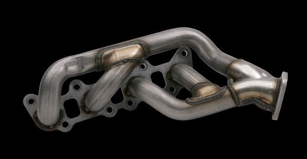
By the way, here's how Ford Coyote team solved the 90-degree exhaust interference problem in a similarly space constrained situation:
An area where the Coyote breaks from the modular pack is its pulse-separated, tubular headers. While hardly the first tubular Ford headers, these intelligently tuned manifolds represent a deep commitment to making power. Doggedly designed, protected from both axe-wielding finance men and dent-prone assembly plants, then nurtured by patient calibration engineers, these headers visibly represent the willing-to-bleed-for-it dedication the Coyote team had toward making power.
Technically, Coyote headers are a short Tri-Y design complicated by the Coyote firing order differing from other Blue Oval V-8s and the need to package the catalytic converters close to the engine. We'll let Adam Christian, the team member who designed these headers, as well as the prototype builder who welded up the prototypes in his home garage, tell the Coyote exhaust manifold story as he told it to us.
Adam started by showing us some test results of the current Mustang GT header. "Here's a comparison of a standard cast manifold like on the Three-Valve 4.6 today, which is a nice design. It was hard to beat those manifolds, actually."
"Headers only give you torque, right? That's in general. And while we wanted torque, we needed to sell the manifolds on power. We had already beat our torque target, so advertised power [was the goal]," Adam explained. "When I left racing [Ford Racing], I told the guy, 'I'm going back to production and I'm taking two things with me: headers and valve lofting.' And at least we got one of them into [the Coyote]. We almost loft-it's really close! We basically go to zero force over the nose, but it doesn't actually come unglued."
"So basically the benefits of the tubular headers in a nutshell is about 15 lb-ft and 6 hp," Adam added. "The thing that you'll notice is, you know what a set of Tri-Y headers are supposed to look like-a simple side and a complex side. On all previous Ford engines, the complex side is always on the driver side. This engine is swapped because the firing order is changed. The complex side should be on the passenger side, which is nice for the steering-shaft packaging and everything. What you'll see on these headers though is that we look like we don't know what we're doing, and they are actually simple connectivity on both sides-front pairs, rear pairs, both banks."
"The reason is that you have to have the catalysts very close to the engine-they have to light off-and when you have that kind of length and you try to separate the 90-degree cylinders, which is what you pick for connectivity, you don't have enough length. What ends up happening is you take the blow-down pulse that occurs in the second cylinder, and you push its pulse into the overlap period of that first cylinder, and you actually destroy the volumetric efficiency," Adam continued. "You've helped the pumping because you've moved that pulse out of the pumping portion of that cylinder, but you've hurt its Vol-F [volumetric efficiency] and the net result is zero; you don't get anything for it. And if you look at [Brand T], they're made that way. [Brand C] tends to do just straight-up manifolds. They're nice manifolds, but just straight up."
"This literally was a morning-shower epiphany thing ... you don't know the amount of work [it was] to push that exhaust flange down as far as it is. The catalysts are short. They're actually stacked on top of each other. The bricks have no separation between them at all, they're just crammed together. They touch; there's no cat monitor in-between. Usually there is a HEGO in-between and we don't have it," Adam said. "So we had pushed the package as far as we could and there just wasn't enough length to get it to work, and then I thought, 'What if we just don't try to pair the 90-degree cylinders? What if we just try to bring them together as much as possible?' And that's what you see, particularly the right bank; right-bank cylinders 1 and 2 come right together, and those two fire right on top of each other. You see the secondary pipe is actually bigger than the rest-that's to take the larger blow-down of those two."
"So we've separated the 180-degree cylinders because we have enough length that we have fixed the Vol-F on all those cylinders so they scream. And the 90-degree pairs are also happy in terms of volumetric efficiency-but they have a pumping hit. So that's the best trade-off; basically, if you have to be that short, this is the type you want to have," he said.
"I have to hurry up and apply for a patent on these, 'cause no one else builds them this way," Adam confessed. "Our peak Vol-F, which is at peak torque, is 110 [percent]. It depends on the dyno cell, right, but we've hit as high as 110, 108, so it's pretty impressive. And at peak power we're pretty close to 100. I don't know, typically 98, 99 [percent]."
Certainly the end result is impressive. "Torque is almost 400 lb-ft out of 5.0 liters; no one else comes close. And it's these type of things that help-the intake runner lengths, the port volumes-because we could have gone with a super-short intake and sold out all the torque to go for peak power. It's those small details, the TiVCT, those are the things that let us get that kind of torque," Adam elaborated.
Understanding is the fun part. Every experiment with the actual engine is so time consuming and expensive that it's a no-brainer to try to understand and simulate the engine as thoroughly as possible before taking anything to the metal.
By the way, here's how Ford Coyote team solved the 90-degree exhaust interference problem in a similarly space constrained situation:
An area where the Coyote breaks from the modular pack is its pulse-separated, tubular headers. While hardly the first tubular Ford headers, these intelligently tuned manifolds represent a deep commitment to making power. Doggedly designed, protected from both axe-wielding finance men and dent-prone assembly plants, then nurtured by patient calibration engineers, these headers visibly represent the willing-to-bleed-for-it dedication the Coyote team had toward making power.
Technically, Coyote headers are a short Tri-Y design complicated by the Coyote firing order differing from other Blue Oval V-8s and the need to package the catalytic converters close to the engine. We'll let Adam Christian, the team member who designed these headers, as well as the prototype builder who welded up the prototypes in his home garage, tell the Coyote exhaust manifold story as he told it to us.
Adam started by showing us some test results of the current Mustang GT header. "Here's a comparison of a standard cast manifold like on the Three-Valve 4.6 today, which is a nice design. It was hard to beat those manifolds, actually."
"Headers only give you torque, right? That's in general. And while we wanted torque, we needed to sell the manifolds on power. We had already beat our torque target, so advertised power [was the goal]," Adam explained. "When I left racing [Ford Racing], I told the guy, 'I'm going back to production and I'm taking two things with me: headers and valve lofting.' And at least we got one of them into [the Coyote]. We almost loft-it's really close! We basically go to zero force over the nose, but it doesn't actually come unglued."
"So basically the benefits of the tubular headers in a nutshell is about 15 lb-ft and 6 hp," Adam added. "The thing that you'll notice is, you know what a set of Tri-Y headers are supposed to look like-a simple side and a complex side. On all previous Ford engines, the complex side is always on the driver side. This engine is swapped because the firing order is changed. The complex side should be on the passenger side, which is nice for the steering-shaft packaging and everything. What you'll see on these headers though is that we look like we don't know what we're doing, and they are actually simple connectivity on both sides-front pairs, rear pairs, both banks."
"The reason is that you have to have the catalysts very close to the engine-they have to light off-and when you have that kind of length and you try to separate the 90-degree cylinders, which is what you pick for connectivity, you don't have enough length. What ends up happening is you take the blow-down pulse that occurs in the second cylinder, and you push its pulse into the overlap period of that first cylinder, and you actually destroy the volumetric efficiency," Adam continued. "You've helped the pumping because you've moved that pulse out of the pumping portion of that cylinder, but you've hurt its Vol-F [volumetric efficiency] and the net result is zero; you don't get anything for it. And if you look at [Brand T], they're made that way. [Brand C] tends to do just straight-up manifolds. They're nice manifolds, but just straight up."
"This literally was a morning-shower epiphany thing ... you don't know the amount of work [it was] to push that exhaust flange down as far as it is. The catalysts are short. They're actually stacked on top of each other. The bricks have no separation between them at all, they're just crammed together. They touch; there's no cat monitor in-between. Usually there is a HEGO in-between and we don't have it," Adam said. "So we had pushed the package as far as we could and there just wasn't enough length to get it to work, and then I thought, 'What if we just don't try to pair the 90-degree cylinders? What if we just try to bring them together as much as possible?' And that's what you see, particularly the right bank; right-bank cylinders 1 and 2 come right together, and those two fire right on top of each other. You see the secondary pipe is actually bigger than the rest-that's to take the larger blow-down of those two."
"So we've separated the 180-degree cylinders because we have enough length that we have fixed the Vol-F on all those cylinders so they scream. And the 90-degree pairs are also happy in terms of volumetric efficiency-but they have a pumping hit. So that's the best trade-off; basically, if you have to be that short, this is the type you want to have," he said.
"I have to hurry up and apply for a patent on these, 'cause no one else builds them this way," Adam confessed. "Our peak Vol-F, which is at peak torque, is 110 [percent]. It depends on the dyno cell, right, but we've hit as high as 110, 108, so it's pretty impressive. And at peak power we're pretty close to 100. I don't know, typically 98, 99 [percent]."
Certainly the end result is impressive. "Torque is almost 400 lb-ft out of 5.0 liters; no one else comes close. And it's these type of things that help-the intake runner lengths, the port volumes-because we could have gone with a super-short intake and sold out all the torque to go for peak power. It's those small details, the TiVCT, those are the things that let us get that kind of torque," Adam elaborated.
I was wondering about these headers when I saw them on the new Shelby GT-350 I drove at a Ford track day experience at Laguna...
Interesting modeling, keep up the fact quest, it's good reading and learning.
I was wondering about these headers when I saw them on the new Shelby GT-350 I drove at a Ford track day experience at Laguna... Interesting modeling, keep up the fact quest, it's good reading and learning. Cheers!
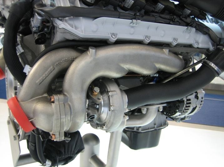
If you liked the Coyote exhaust manifold, this Brabus turbo exhaust manifold is going to blow your mind:
This full simulation system EngMod4T that can simulate all eight cylinders is a real eye opener. Many things that I thought were a problem with the intake are actually a problem with the exhaust. After staring at those simulated traces, the Brabus manifold now makes sense to me. The "wrong way" Ford Coyote 4-2-1 exhaust manifold makes sense. Why long tube headers on a V8 need to have some minimum primary length and after that primary length doesn't really matter becomes clear in the exhaust simulations. Why headers are often stepped and where they are stepped makes now sense. Why bore spacing is important for header type. Why exactly equal length doesn't seem to be that important for headers. Etc.
Let me suggest a completely crazy header configuration that would really drop some jaws. With the 928 firing order, join 1&3 as early as possible. Then run three pipes, two small ones and one bigger one, down to the 3-1 collector On the driver side, join 5&6 as early as possible. Then similarly run two small pipes and one big pipe to the 3-1 collector. That would be the weirdest looking header on a 928! But it's basically just a copy of the Ford Coyote header trick that allowed them to get over 400 hp. Like the Coyote designer said: "So we've separated the 180-degree cylinders because we have enough length that we have fixed the Vol-F on all those cylinders so they scream. And the 90-degree pairs are also happy in terms of volumetric efficiency-but they have a pumping hit. So that's the best trade-off; basically, if you have to be that short, this is the type you want to have."
I was wondering about these headers when I saw them on the new Shelby GT-350 I drove at a Ford track day experience at Laguna...
By the way, the Shelby GT-350 has a flat plane crank. It doesn't have 90, 180, and 270 degree separation pulses per bank like Coyote. Instead, it has 180 degree pulses only. That's why those Shelby GT-350 manifolds are a little bit different. They only need to add enough physical distance between the cylinders firing 180 degrees apart.
It's a strange day and age when the car factory CNC ports the heads and puts them on a flat crank V8 and then sends the result to showroom.
The pictures are nice, thanks. Certainly very interesting. Me looking at them is a little bit like a dog watching a TV, but like the dog I'm still enjoying it! ;-) I notice some intentional grooving on the exhaust port roof, I wonder what that's all about. Also the intake port floor being cut relatively flat is similar to what Ake is doing with his heads.
Also the GT-350 flat crank doesn't appear to be just two four banger joined together. Instead it's something different. I think it doesn't shake the same way as a four banger, instead it should rock back and fourth. There's something different in that crank, for sure.
I think the grooving on the intake is for turbulence to mix the fuel and promote better combustion. It may also help with a boundary layer to stop fuel pooling on the runner walls.
Either way, the car rocks with that motor. $65k will surely see them all sold. Btw, the gt350R comes with carbon fiber wheels.....
I would prefer the counterweights on the crank to be boat tailed and have an aero foil shape. But, it works as is...
On another note, the Ferrari V8 is also something.. A buddy just got a California T, and will be one of the first 5 recipients of a 488 spider in spring. Can't wait to drive the 488. The California T is pretty decent, but the 488 should be special... I will post some feedback on the 488 turbocharged motor after I drive it...
I think the grooving on the intake is for turbulence to mix the fuel and promote better combustion. It may also help with a boundary layer to stop fuel pooling on the runner walls.
But what are those exhaust port grooves all about?!
Originally Posted by blau928
I would prefer the counterweights on the crank to be boat tailed and have an aero foil shape. But, it works as is...
As Erkka noted above, the crank is different from the usual flat plane V8 crank. Why, who knows?
Not sold on the knife edging, bull nosing, etc. of cranks. High end racing doesn't seem to be doing any of that. To the extent that it helps in some dyno tests, it probably helps because it by coincidence makes the main bearing loads more even and friction lower.
In terms of counterweight design, making the counterweight outline flatter than a circle with an origin at the crank centerline is an interesting innovation. Usually, if you look at the old cranks, the counterweights are as if they'd been turned down on a lathe. That may not be optimal, however, if the binding constraint is the piston to counterweight clearance. A flatter curve will work better, as the piston is only very close to the crankshaft counterweight at the BDC and one can have the counterweights grow to a longer radius circle as teh angle from the plane running from the rod journal centerline thru the crank centerline grows. Probably not very applicable to the 928 cranks since the deck height is too long to start with and the girdle is the binding constraint on the counterweight maximum radius...
I think the exhaust groove is also related to boundary layer, as it guides the flow within the boundary layers rather than have the charge develop irregular vortices on the way out of the head and slow the velocity of the charge exit.
One point I forgot to mention, is that in a crankcase with a vacuum, the shaped counterweights won't matter as there is little/no resistance in a vacuum/dry sump race motor.

 10-10-2015, 08:52 PM