When you click on links to various merchants on this site and make a purchase, this can result in this site earning a commission. Affiliate programs and affiliations include, but are not limited to, the eBay Partner Network.
hard to tell in the photos...do your rods more resemble right or left? Left is 944 cast, right is 944 turbo forged.
The 928 rods in the blue engine look like the 944 turbo precision powder forged rods. They don't look like the 944 cast rods. This appearance is almost entirely explained by the fact that they are precision powder forged rods and not cast rods! ;-). You can see that clearly from the assembled short block photos above.
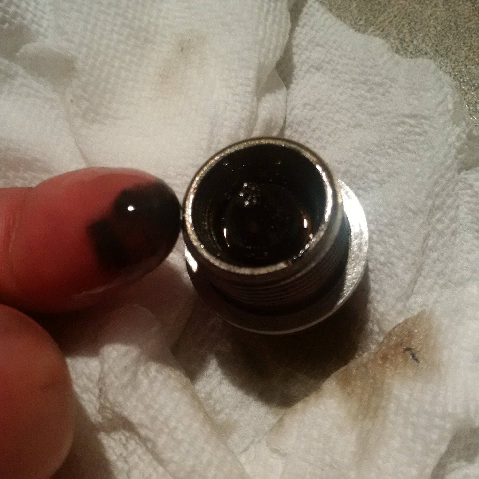
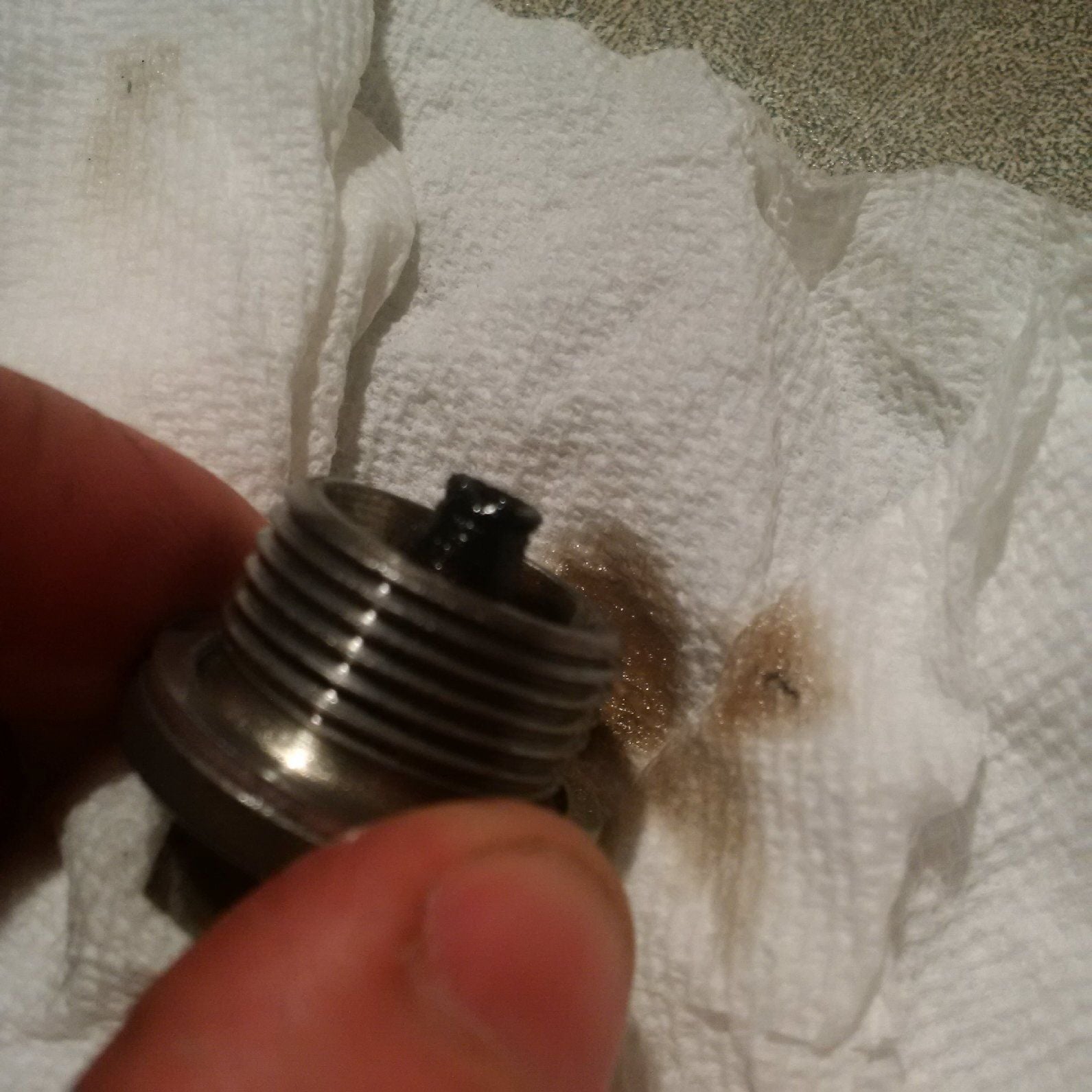
In contrast, this is a 928 cast rod, which is not what the blue engine has:
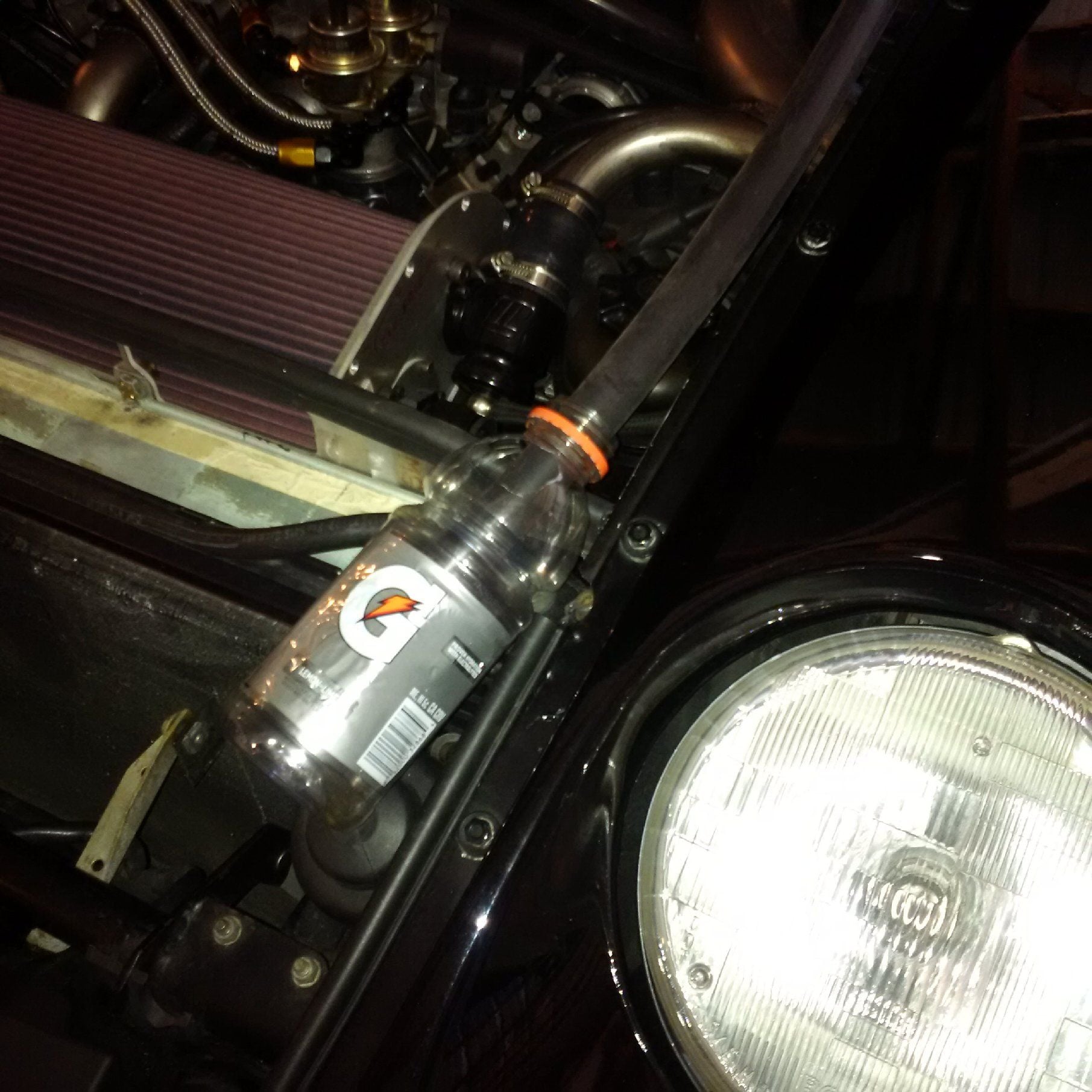
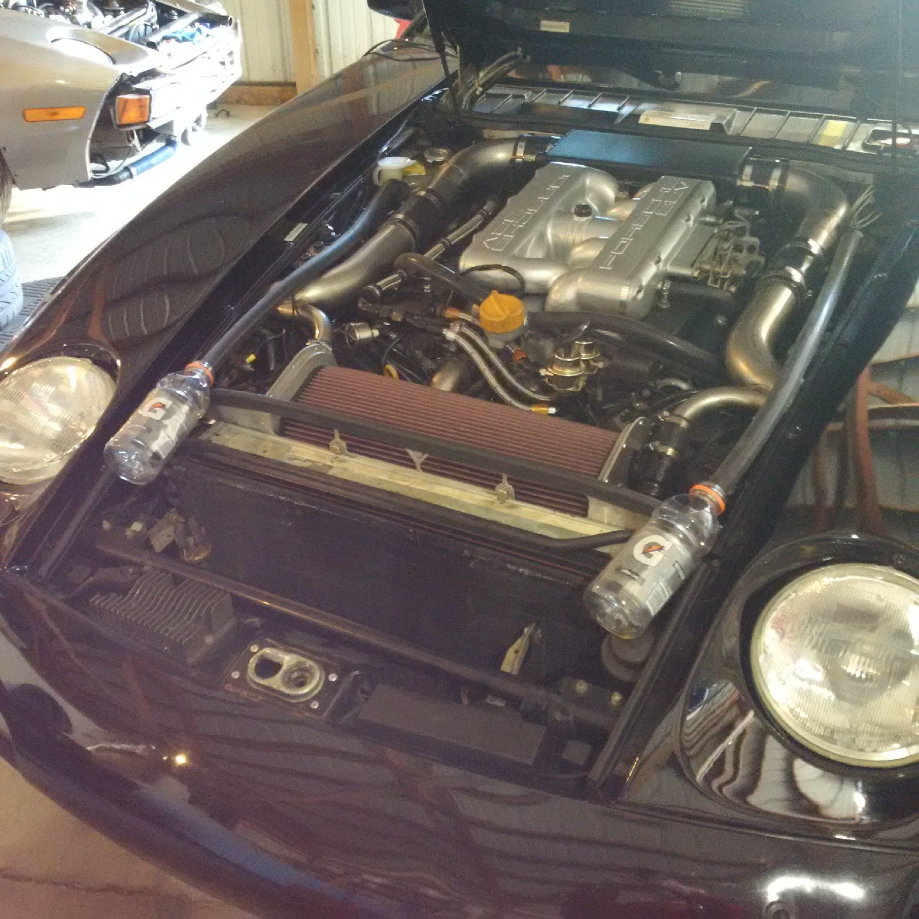
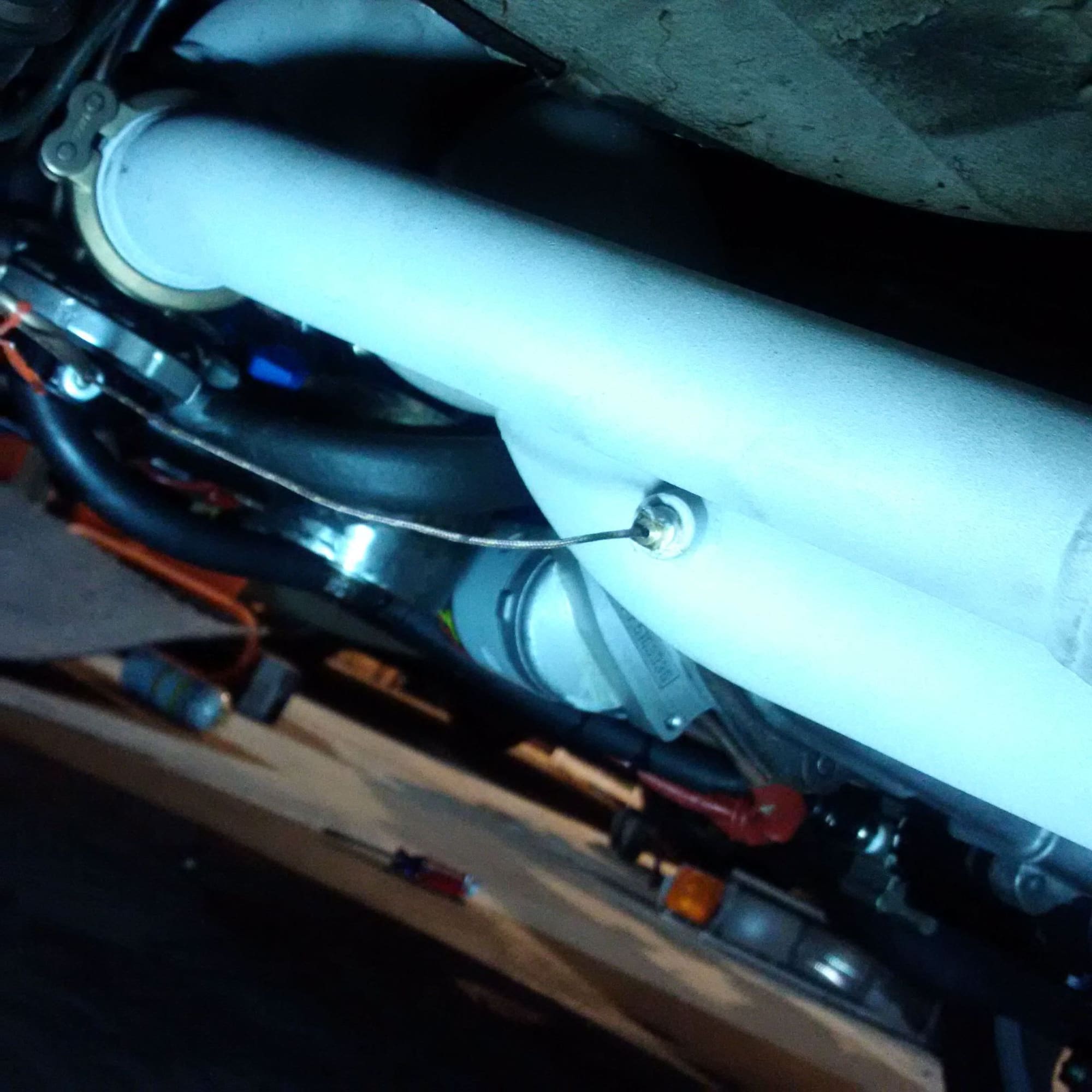
The crankcase breather is hooked up and we're running an old school final experiment on how well the system works:
I say say old school experiment because a more modern high tech test would use the lower carbohydrate G2 bottles.
are those oil vapors fruit punch, or lemon-lime?
can we call your breather system "the knock quencher"
are those oil vapors fruit punch, or lemon-lime? can we call your breather system "the knock quencher"
We'll see how it works. The turbo blowby is higher than I expected and used in the design computations, so we'll see if the breather system works. It should work, though.
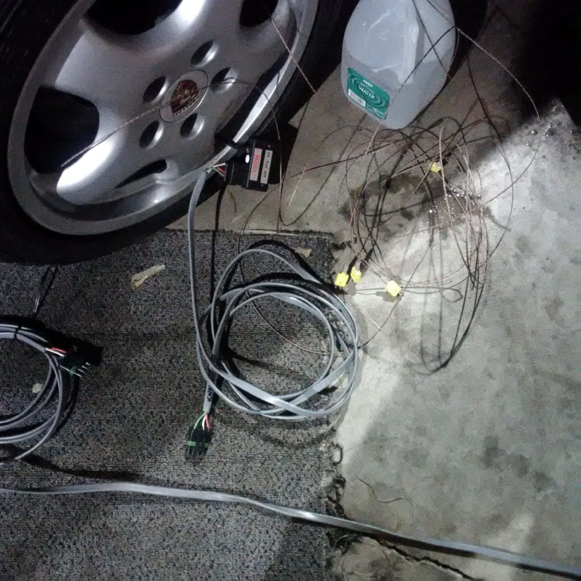
We're one sensor extension cable away from running this on the dyno with boost.
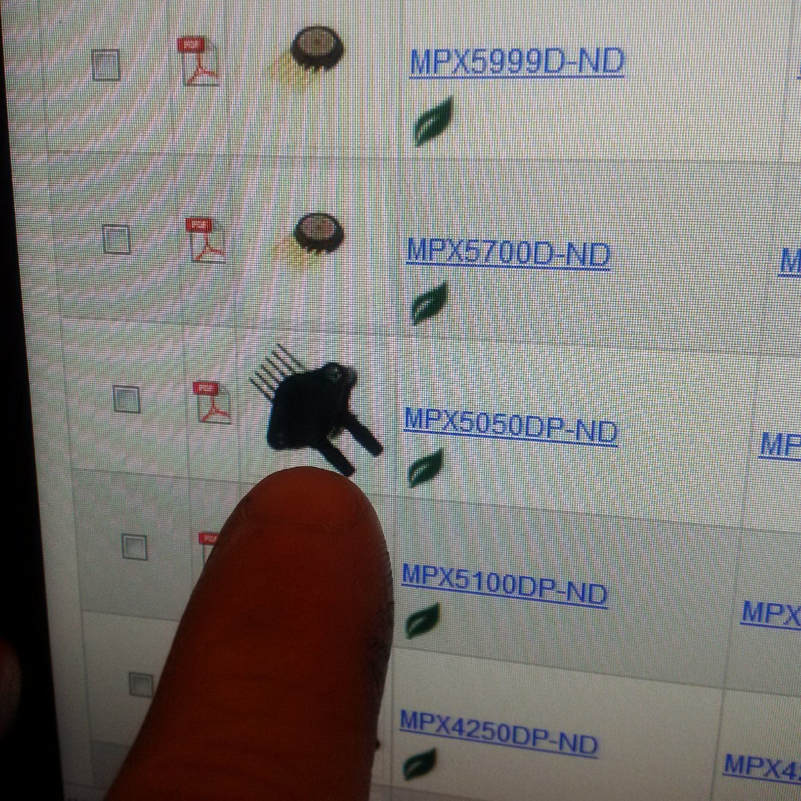
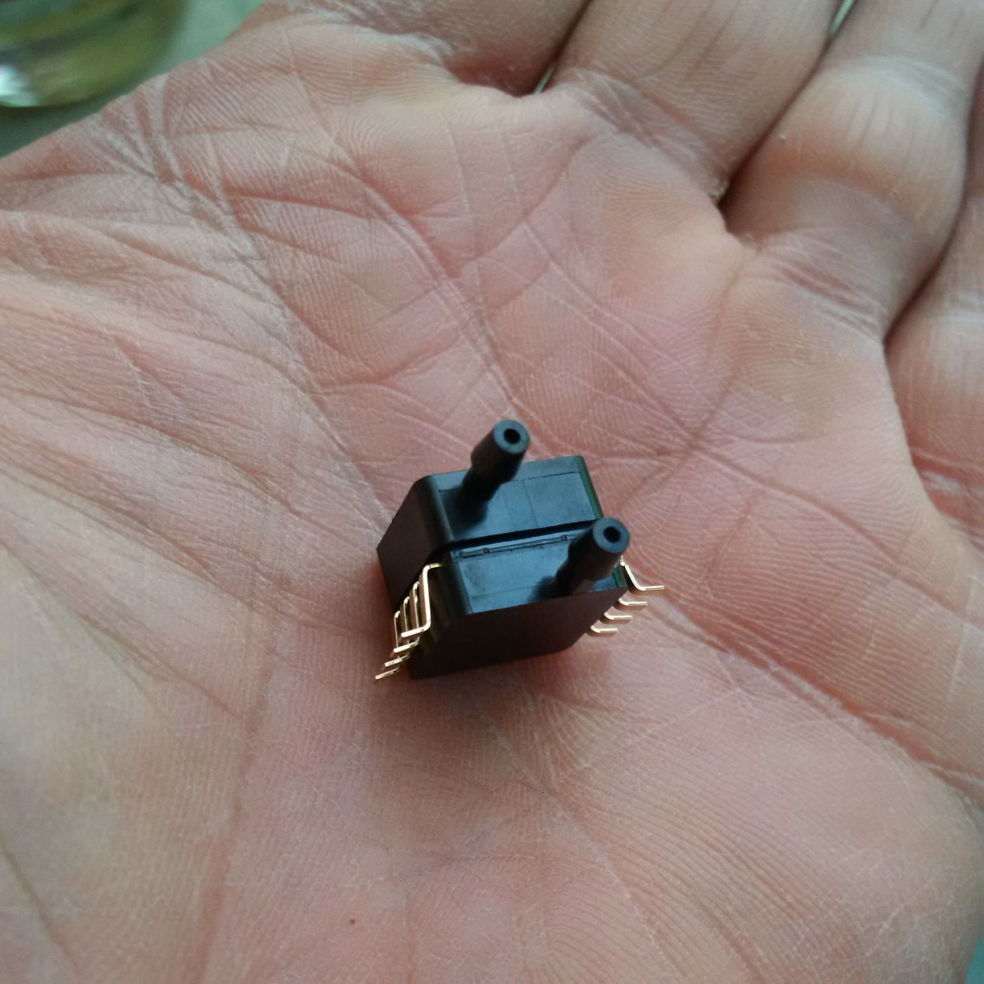
The pressure sensors:
Ambient pressure from the weather station
Left hand side compressor inlet pressure
Left hand side intercooler inlet-outlet pressure differential
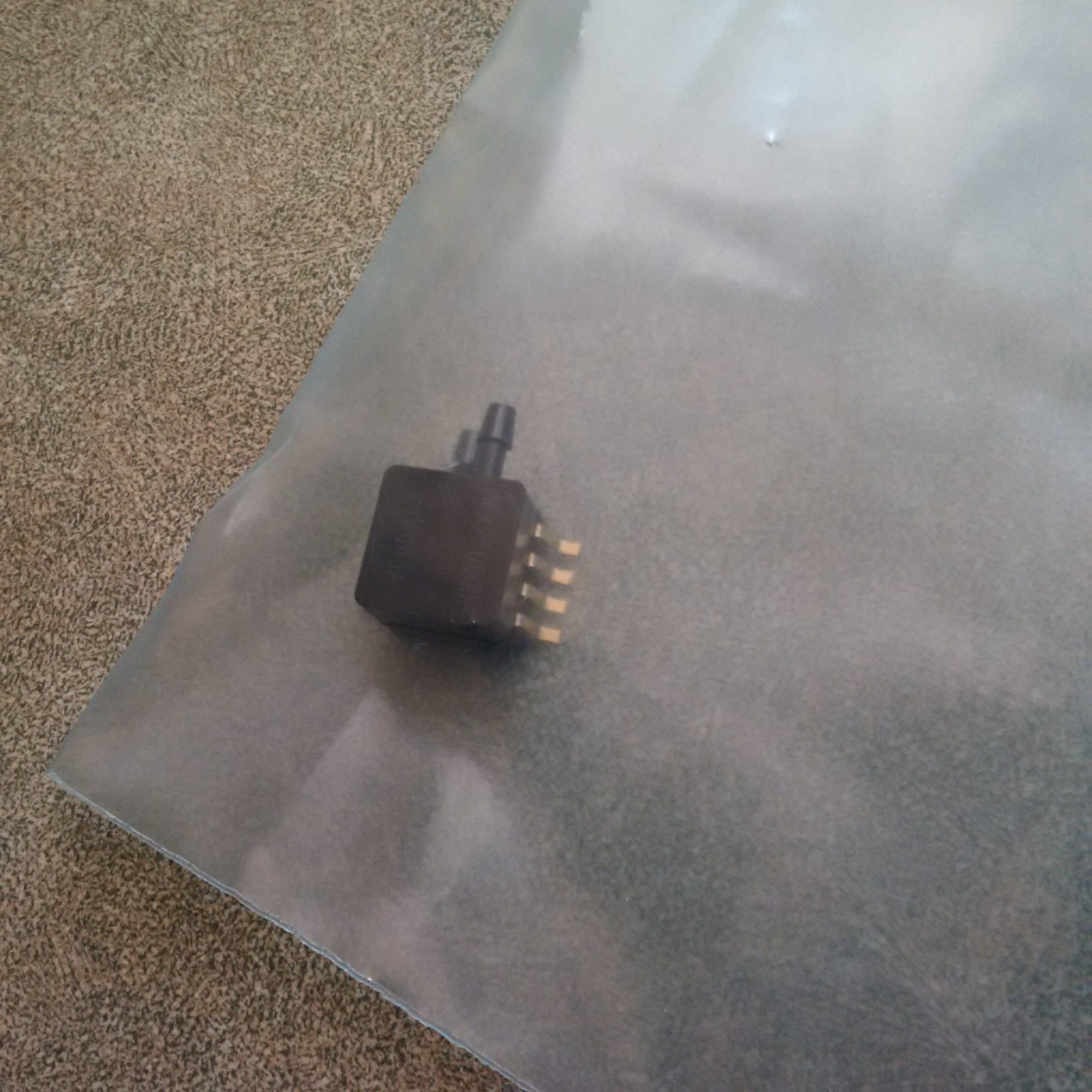
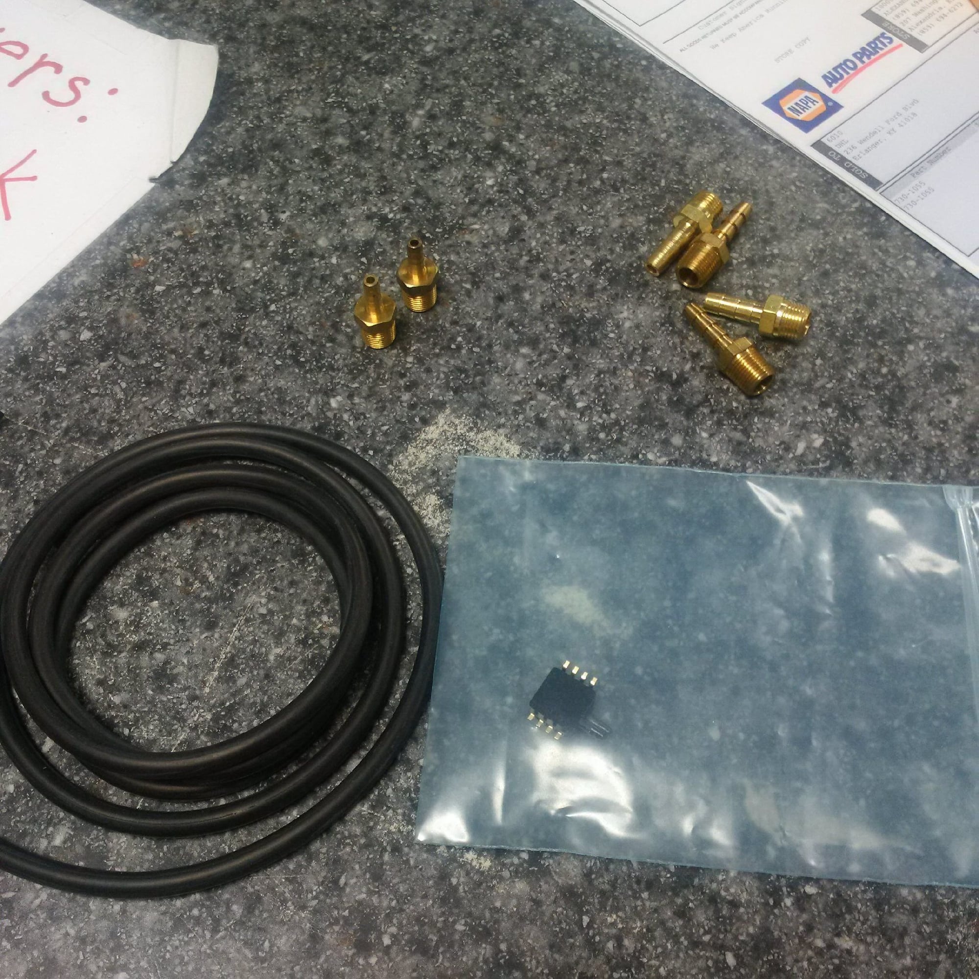
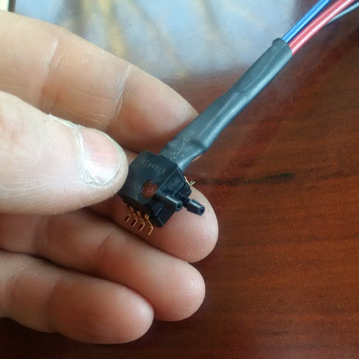
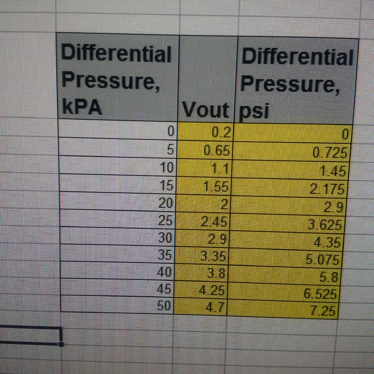
The extension cord is in but one of the pressure differential sensors has the wrong range. Can't measure the intercooler pressure drop with a 7 bar pressure differential sensor, at least I hope you can't. John is ordering a sensor in the right range.
This build might be on the edge at high boost, so we want all the basic sensors operational before running it. It'd be shame to blow it up without getting the basic data about the external turbo system.
Sensor is in so we're close to showtime!
This sensor is for the intercooler pressure drop. The intercooler design was a complicated compromise, and it'll be interesting to see how much pressure drop the dual pass design results in.
The most useful measurement will be the downpipe pressure measurement. This is because we need to make a new exhaust and it'll be useful to know whether we have to go to 3.5" pipes after the wastegate merge.
I see your using K type thermocouples. Are the temperature ranges that high on turbo and exhaust applications? Is this normal on automotive Instrumentation?
I see your using K type thermocouples. Are the temperature ranges that high on turbo and exhaust applications? Is this normal on automotive Instrumentation?
Up to 1000C in the exhaust manifold, I think, but hopefully not quite that high.
John passed me an email question on the crankcase breather system. Loosely quoting:
"If I am reading this right, the system has been tested to atmosphere and there is about 2 cfm of blowby, which is great. But if you hook the outlet of the separators to the area behind the air-filters, the separator outlet is going to see about 2" hg. Does not seem like much but your going from atmosphere (14.7 psi) to atmosphere minus 2" hg."
The crankcase breather system is sized for a much larger blowby quantity than 2 CFM. It would have easily handled much higher blowby rate, but the blue engine was just built to be so damn tight! The two hoses are large, and the BMW separators are each sized for a relatively large six cylinder engine.
The air filter is not restrictive, so the filter will highly likely see a pressure drop less than 2 inches of mercury at our flow rates. I'd guess less than half that given the massive surface area. I'm guessing less than 1" hg at full load, which is one sixth of the pressure drop between sea level and Denver, Colorado.
However, suppose it does pull that vacuum. The system will draw up to 2" vacuum into the crankcase, which is like driving 1/3 the elevation to Denver. This will not impact the blowby gas flow rate in mass or SCFM units in meaningful way, because the pressure differential between the cylinder and the crankcase doesn't change much. The blowby might go down a tiny bit because of minimally improved ring seal? 2" vacuum in the crankcase will somewhat reduce oil entrained in the crankcase gas and thus blowby, that is it might help a little bit, but the effect will be trivially small.
I'd love to pull more of a vacuum in the crankcase as anything up to at least 8" hg would make everything better and nothing worse, but unfortunately this breather system will only see similar outlet vacuums to what the stock S4 system sees at the MAF elbow.

 02-23-2017, 10:49 AM