
Timing Belt and Water Pump Procedure w/pics
 01-01-2010, 02:20 PM
#1
Rennlist Member
Thread Starter
Join Date: Sep 2007
Location: Ridgecrest, California
Posts: 1,363
Likes: 0
Received 143 Likes
on
28 Posts
Between the timing belt and water pump repair I did on Virginia last winter and the Water Pump block repair procedure I did on Virginia a couple of months ago, I had enough pics to document the TB and WP procedure so thought I'd share the process I followed. I'm not an expert mechanic by any means but wanted to show the step by step process as a pictorial guide for other newbies such as myself that may want to try this maintenance procedure themselves.
There's quite a few pics in this writeup (appox. 405) and it's "Newbie Rated" (i.e., a lot of detail). Therefore, I thought I'd try something new to make it easier to find material in the writeup more directly. I've broken the entire process into Chapters and will preceed each post that starts a new Chapter with a heading that you can find easily with the search function. For example, if you want to see the section on Removing and Repairing Timing Belt Tensioner, search for "CH14". A table of contents has been added that includes the Chapter number and title for reference. Special tools and Parts section is also included.
This procedure is for a 1987 (early) S4 928 (vin 0349) - our "Virginia" that volunteered for the procedure. OH, one last disclaimer, there may be a few pictures of dirty parts from before I had a chance to clean.
Table of Contents:
CH01 Parts, Tools, and Preparation
CH02 Draining Coolant and Removing Coolant Hoses
CH03 Removing Accessory Belts
CH04 Removing Fan Shroud
CH05 Removing Power Steering Pump and Alternator
CH06 Removing Upper Cam Gear Covers, Setting Crank at 45 Degrees BTDC
CH07 Removing Accessory Belt Pulleys and Center Timing Belt Cover
CH08 Removing Tensioner Pulley and Timing Belt
CH09 Removing Water Pump
CH10 Removing Oil Pump Gear and Rear Timing Belt Cover
CH11 Removing Oil Pump and Replacing O-Rings
CH12 Installing Rear Timing Belt Cover and Oil Pump Gear
CH13 Repairing/Replacing Tensioner Pulley and Tensioner Bushings
CH14 Removing and Repairing Timing Belt Tensioner
CH15 Installing Water Pump
CH16 Installing Timing Belt Tensioner
CH17 Installing Timing Belt Tensioner Pulley
CH18 Installing Timing Belt and Setting Tension
CH19 Installing Center Timing Belt Cover and Routing Engine Harness
CH20 Filling Tensioner with Gear Oil
CH21 Installing Power Steering Pump and Alternator
CH22 Installing Upper Cam Gear Covers
CH23 Installing Fan Shroud
CH24 Installing Accessory Belts and Pulleys
CH25 Installing Distributor Caps, Dipstick, Spark Plug Wires
CH26 Installing Coolant Hoses
CH27 Wrap Up
Here we go.....
Continued.....
 01-01-2010, 02:24 PM
#2
Rennlist Member
Dwayne, at the risk of sounding like a broken record, you ARE the man. Thank you so much for taking the exhorbitant amount of time it must have taken to do this.
I know many of us would not be able to own these fine cars without the support and friendship of the more knowledgeable members and vendors on this site.
I'm going to be doing my w/p timing belt job sometime this winter or spring. This is very timely.
Thanks again, and Happy New Year! -Ed
I know many of us would not be able to own these fine cars without the support and friendship of the more knowledgeable members and vendors on this site.
I'm going to be doing my w/p timing belt job sometime this winter or spring. This is very timely.
Thanks again, and Happy New Year! -Ed
01-01-2010, 02:48 PM
#3
Rennlist Member
Thread Starter
Join Date: Sep 2007
Location: Ridgecrest, California
Posts: 1,363
Likes: 0
Received 143 Likes
on
28 Posts
For this procedure, I replaced the following parts. You do not have to replace all the parts I did for this procedure and you may find you want to replace a few optional parts that I did not replace in this procedure. After you have "dug into" the job, you may want to assess your specific situation on what to replace. However, if you know you will be replacing certain parts, it's recommended that you order the parts you will be replacing ahead of time so they are available and ready when you start work.
Parts:
Timing Belt
Water Pump
Water Pump Gasket
Tensioner Boot and Clamp
Tensioner-to-Block Gasket
Tensioner Piston O-Ring
Tensioner Pulley
Tensioner Bushings
Oil Pump O-Ring
Oil Pump Bolt O-Rings (3)
Anti-Freeze/Coolant and Distilled Water
90w Gear Oil
Optional Parts (instructions not included in this procedure)
Tensioner Idler Pulley
Front Crank Shaft Seal
Front Oil Pump Seal
Most of the Special Tools I used include:
Timing Belt Tensioner Tool (Kempf Tool)
Flywheel Lock Tool
2-Jaw, 3-Jaw, Power Steering Pulley Pullers
Breaker Bar and Torque Wrench capable of 295 Nm (217 Ftlbs)
Medium sized prybar and gasket scraper
Preparation:
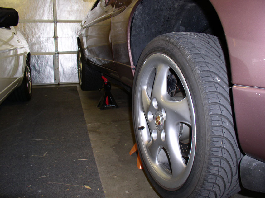
I used Porken's lift bars to lift and support the car. Harbor Freight has some excellent heavy duty jackstands that work well for this application. Lift and support the car so there is plenty of room underneath to work.
Next, install service covers (if you have them) or other suitable covers for your fenders and front bumper.
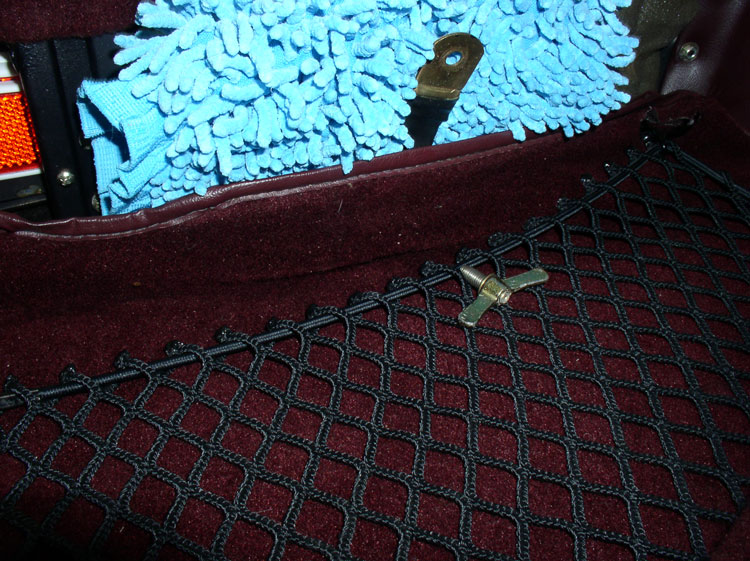
Then, disconnect the negative cable on the battery. I usually remove the spare tire and remove the cable from the battery post. However, this time I decided to "live on the edge" and disconnect the negative battery cable from the grounding point behind the tool cover as you can see from the pic below.
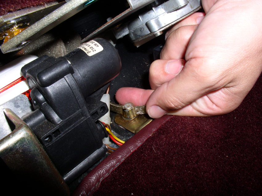
Once the cable is detached, I placed a thick barrier between it and any possible grounding points. All in all, I think I prefer to go the extra steps and disconnect the cable from the battery. But you never know what you like best until you try something different!
Next remove both belly pans. From the factory, the rear pan is aluminum while the front pan is a plastic composite. Remove the rear pan first.
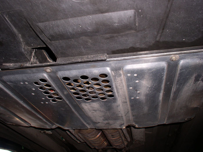
The rear pan is held on by nine (9) 8mm screws. Three across the front, four across the back and one on each side. When the screws are removed, you will need to slide the pan rearward to clear the front belly pan.
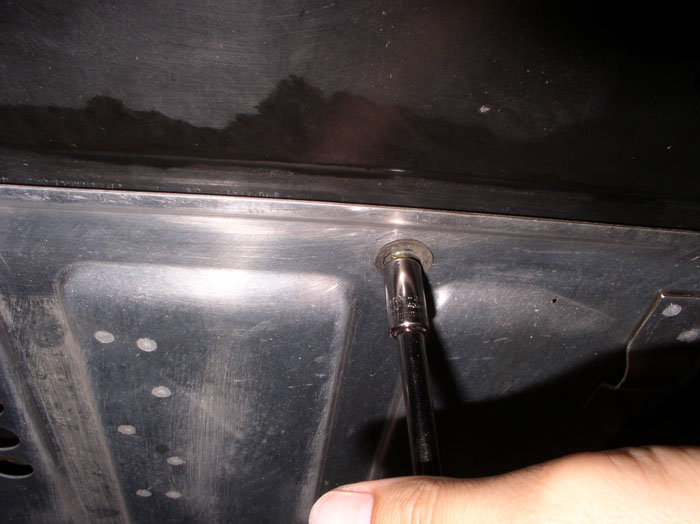
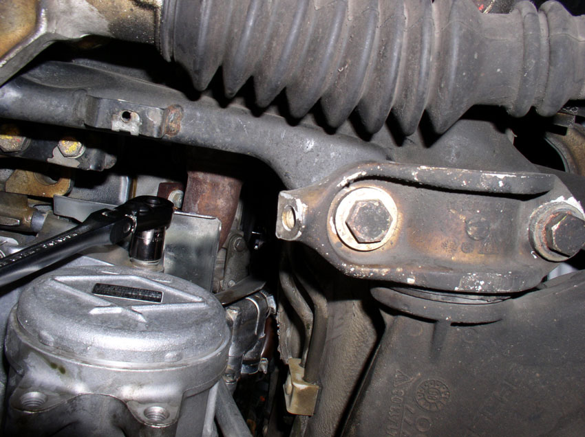
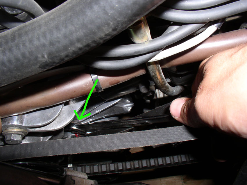
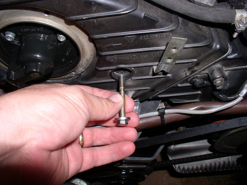
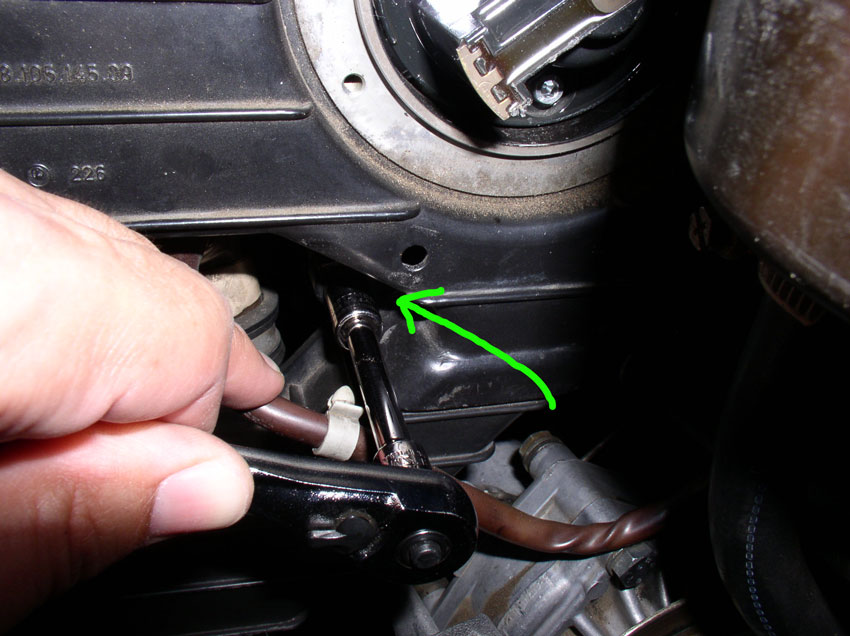
The front pan also has nine (9) 8mm screws AND two (2) 10mm bolts. Five across the front of the pan, one on each side of the pan and two 8mm screws counter sunk in these holes pictured below. Remove the 9 8mm screws first...
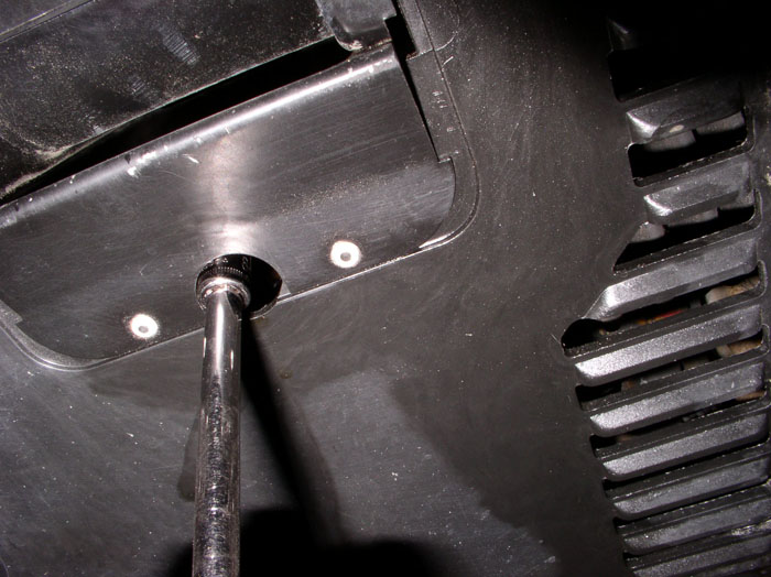
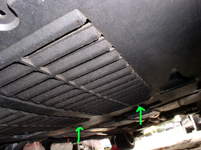
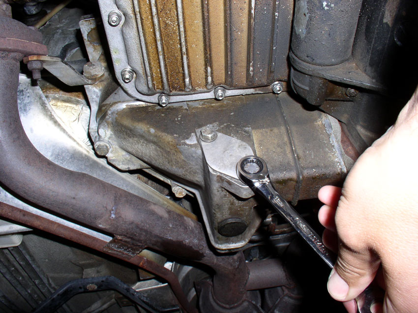
...then remove the two remaining 10mm bolts (see arrows in pic below) while holding the belly pan up with one hand. Lower the belly pan and place both out of the way.
Continued.....
Parts:
Timing Belt
Water Pump
Water Pump Gasket
Tensioner Boot and Clamp
Tensioner-to-Block Gasket
Tensioner Piston O-Ring
Tensioner Pulley
Tensioner Bushings
Oil Pump O-Ring
Oil Pump Bolt O-Rings (3)
Anti-Freeze/Coolant and Distilled Water
90w Gear Oil
Optional Parts (instructions not included in this procedure)
Tensioner Idler Pulley
Front Crank Shaft Seal
Front Oil Pump Seal
Most of the Special Tools I used include:
Timing Belt Tensioner Tool (Kempf Tool)
Flywheel Lock Tool
2-Jaw, 3-Jaw, Power Steering Pulley Pullers
Breaker Bar and Torque Wrench capable of 295 Nm (217 Ftlbs)
Medium sized prybar and gasket scraper
Preparation:
I used Porken's lift bars to lift and support the car. Harbor Freight has some excellent heavy duty jackstands that work well for this application. Lift and support the car so there is plenty of room underneath to work.
Next, install service covers (if you have them) or other suitable covers for your fenders and front bumper.
Then, disconnect the negative cable on the battery. I usually remove the spare tire and remove the cable from the battery post. However, this time I decided to "live on the edge" and disconnect the negative battery cable from the grounding point behind the tool cover as you can see from the pic below.
Once the cable is detached, I placed a thick barrier between it and any possible grounding points. All in all, I think I prefer to go the extra steps and disconnect the cable from the battery. But you never know what you like best until you try something different!
Next remove both belly pans. From the factory, the rear pan is aluminum while the front pan is a plastic composite. Remove the rear pan first.
The rear pan is held on by nine (9) 8mm screws. Three across the front, four across the back and one on each side. When the screws are removed, you will need to slide the pan rearward to clear the front belly pan.
The front pan also has nine (9) 8mm screws AND two (2) 10mm bolts. Five across the front of the pan, one on each side of the pan and two 8mm screws counter sunk in these holes pictured below. Remove the 9 8mm screws first...
...then remove the two remaining 10mm bolts (see arrows in pic below) while holding the belly pan up with one hand. Lower the belly pan and place both out of the way.
Continued.....
01-01-2010, 03:21 PM
#4
Rennlist Member
Join Date: Oct 2005
Location: Gatineau, Qu�bec, Canada
Posts: 5,136
Received 1,207 Likes
on
467 Posts
Like Ed said, yes YOU ARE THE MAN! 
Thank you so mutch for doing all that for us.
Now I have everything I need to do the job myself when it will be due in 2011.
Happy New Year to all.
Thank you so mutch for doing all that for us.
Now I have everything I need to do the job myself when it will be due in 2011.
Happy New Year to all.
01-01-2010, 03:27 PM
#5
Rennlist Member
Thread Starter
Join Date: Sep 2007
Location: Ridgecrest, California
Posts: 1,363
Likes: 0
Received 143 Likes
on
28 Posts
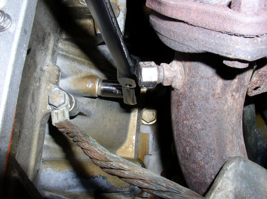
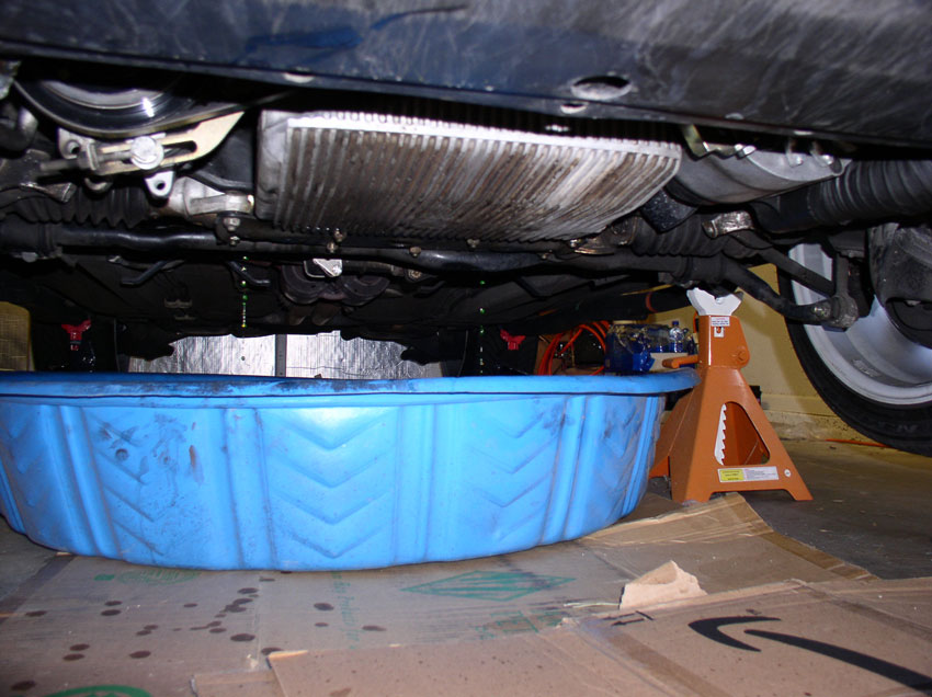
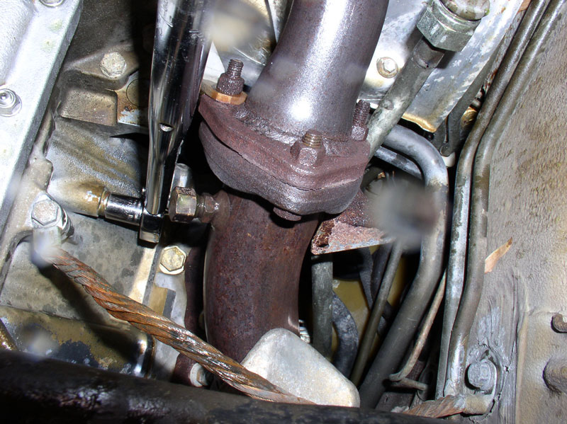
First, I drained the block of coolant. Get a suitable container ready for catching the coolant. I used a small kiddie wading pool. The drain plugs are located one on each side of the block about 3/4 toward the rear of the block. The drain plugs are 13mm bolts. I use a 13mm socket and long handle socket wrench.
Once you take out the bolt, coolant will begin to slowly drain. Go ahead and position the kiddie pool in place under the one bolt you just took out and begin taking out the other bolt on the opposite side of the block. With both bolts out, position the kiddie pool under both drain plugs to catch the coolant as shown below.
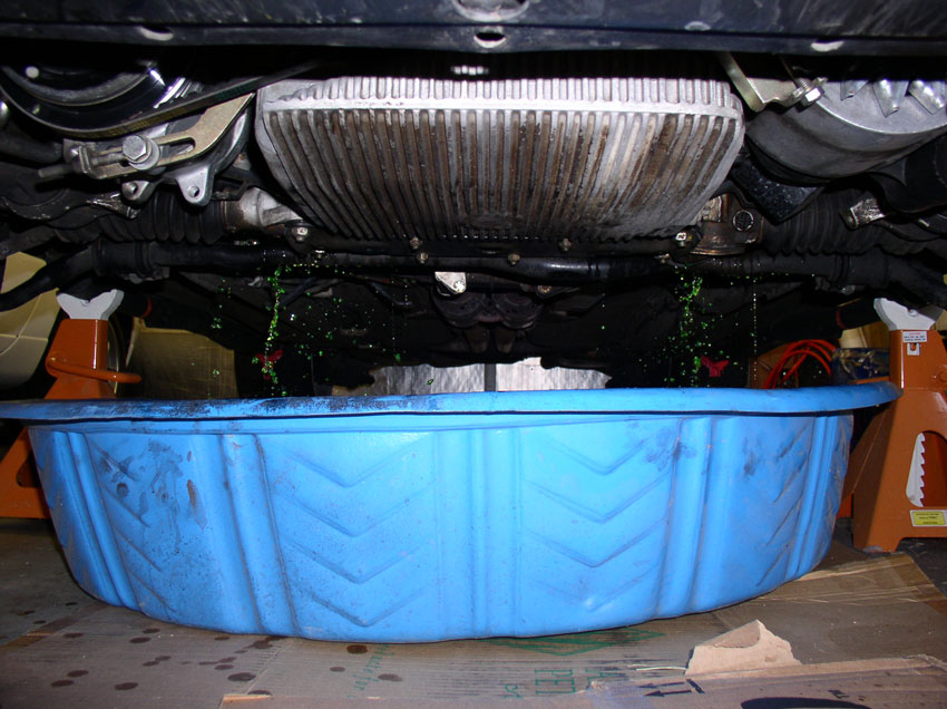
Then go topside, and open the coolant reservior cap.....
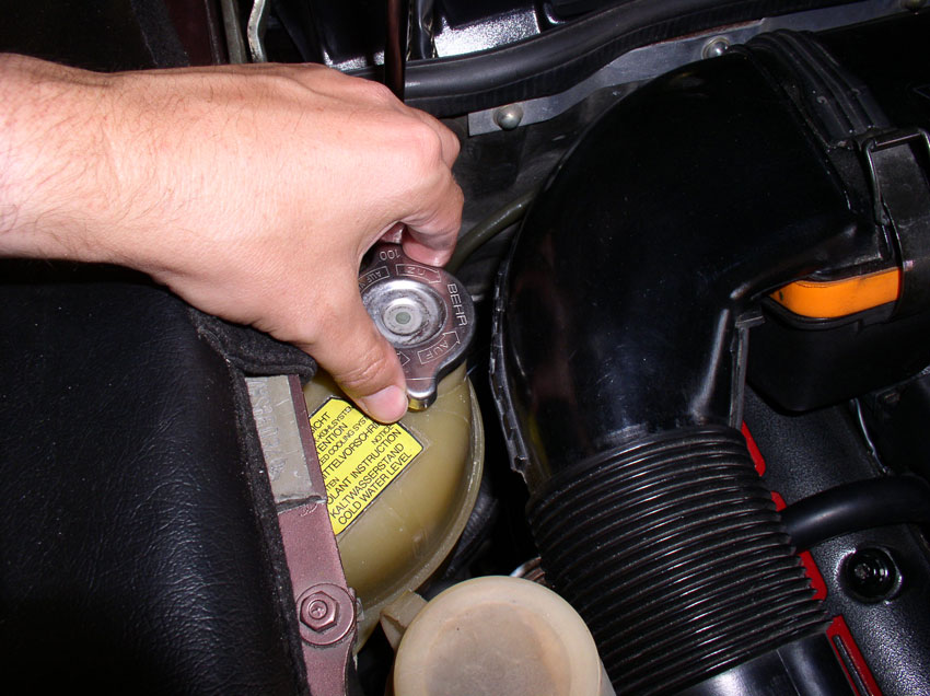
....and the coolant will come out much faster now as seen below.
The coolant bolt is an M12 thread and is coated with copper anti-seize. It also has a sealing ring as can be seen in the pic below. The sealing ring is size 12mm (ID) X 17mm (OD) and is part number 900.123.055.30. The sealing ring should be inspected and replaced when showing signs of wear. I usually replace mine every 3rd time I take the bolt out and re-tighten.
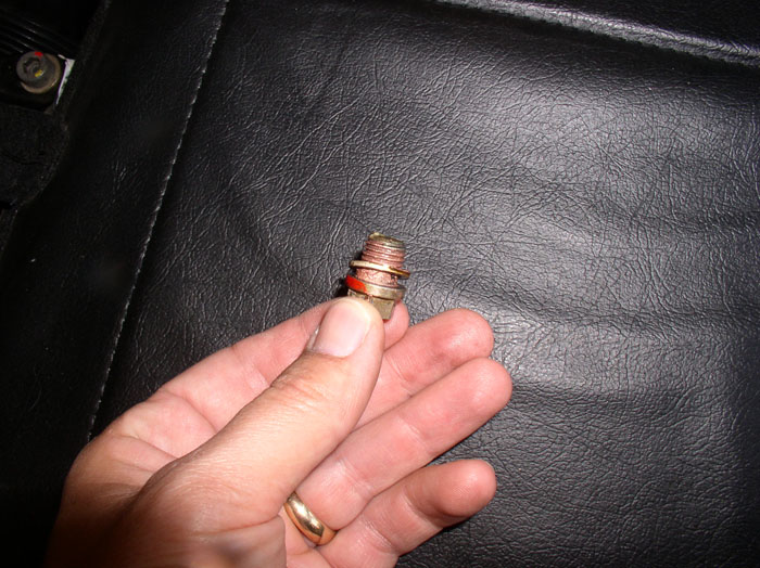
After the coolant has drained from the block, re-install the drain plugs and torque to 35Nm (25.8 Ftlbs).
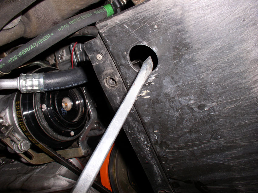
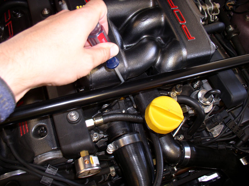
Next, drain the radiator of coolant. The blue drain plug is accessed through the spoiler access hole as pictured below.
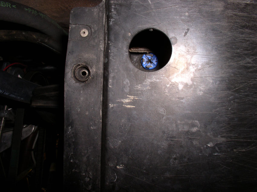
I used a large flat blade screwdriver to take out the screw. Have your kiddie pool or catch can in place while you are taking out the plug. Inspect the plug when removed. Like the sealing rings on the block drain plugs, these plugs have a small o-ring for sealing the radiator drain. Over time they can begin to leak. If you are noticing leaking at the drain port or notice the o-ring is worn or damaged, you can order a new drain plug with o-ring from one of the 928 parts vendors (part number 928.106.444.01). After the radiator is finished draining, replace the drain plug - tightening torque for the blue plastic radiator plug is only 1.5Nm or 1.1 Ftlbs (about 13 inchpounds) (THANKS, John Speake).
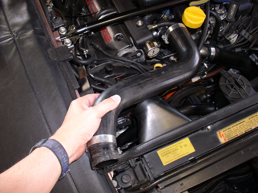
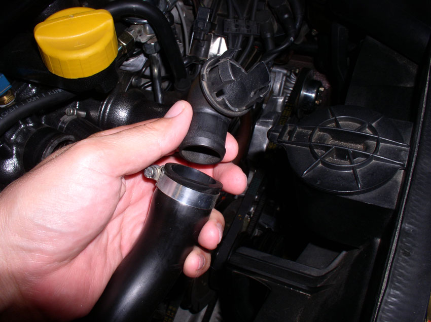
Next, we'll remove the radiator coolant hoses. First, remove the air intake tubes.
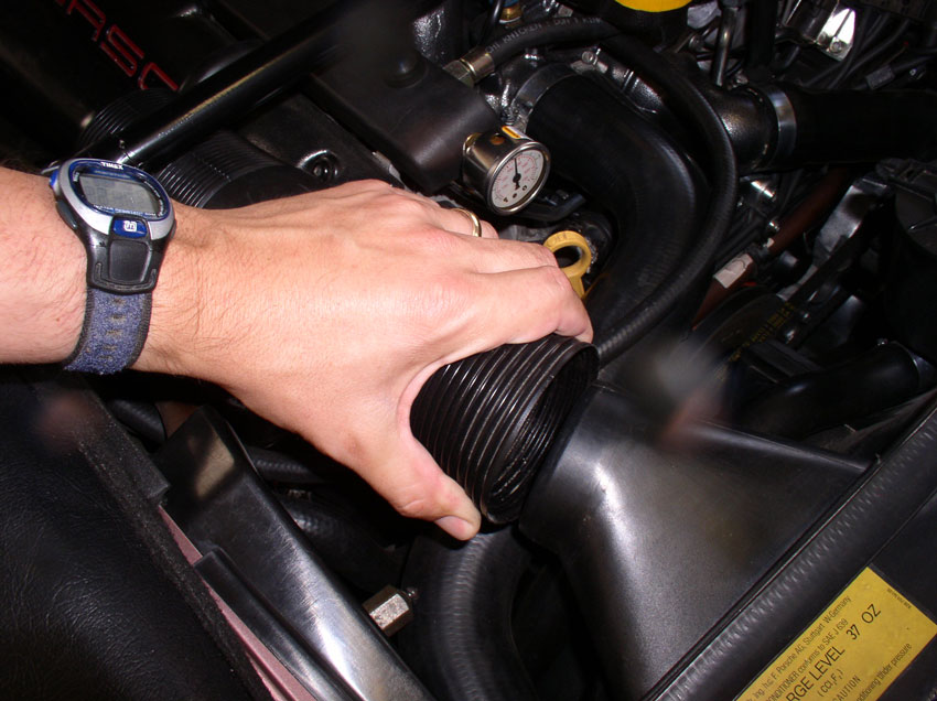
Then, loosen the upper radiator hose clamp at the engine. You can use a flat blade screwdriver or a 10mm socket wrench. Pull the hose off the thermostat housing.
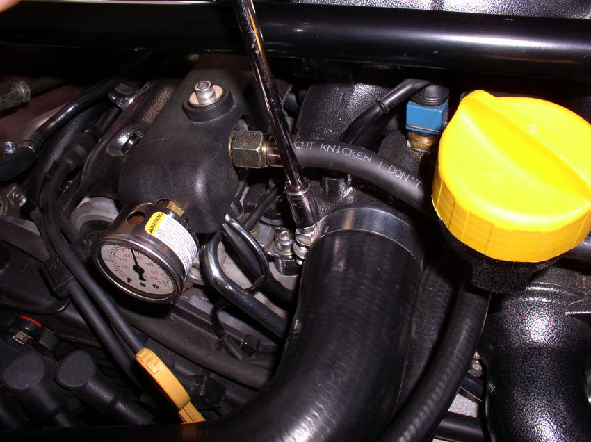
Using a flat blade screwdriver, loosen the clamp on the air bleeder hose also connected to the thermostat housing. You may need a long screwdriver to reach the clamp.
Pull the bleeder hose from the thermostat housing as shown. You can either remove and bag the clamps or tighten them down on the hose after removal so they don't get lost.
Next, remove the fan wiring harness from its connection point on the fan shroud as shown.
Then loosen the clamp on the upper hose at the radiator as shown. Again, I simply used the 10mm socket wrench.
Remove the upper radiator hose and set aside.
Continued.....
Once you take out the bolt, coolant will begin to slowly drain. Go ahead and position the kiddie pool in place under the one bolt you just took out and begin taking out the other bolt on the opposite side of the block. With both bolts out, position the kiddie pool under both drain plugs to catch the coolant as shown below.
Then go topside, and open the coolant reservior cap.....
....and the coolant will come out much faster now as seen below.
The coolant bolt is an M12 thread and is coated with copper anti-seize. It also has a sealing ring as can be seen in the pic below. The sealing ring is size 12mm (ID) X 17mm (OD) and is part number 900.123.055.30. The sealing ring should be inspected and replaced when showing signs of wear. I usually replace mine every 3rd time I take the bolt out and re-tighten.
After the coolant has drained from the block, re-install the drain plugs and torque to 35Nm (25.8 Ftlbs).
Next, drain the radiator of coolant. The blue drain plug is accessed through the spoiler access hole as pictured below.
I used a large flat blade screwdriver to take out the screw. Have your kiddie pool or catch can in place while you are taking out the plug. Inspect the plug when removed. Like the sealing rings on the block drain plugs, these plugs have a small o-ring for sealing the radiator drain. Over time they can begin to leak. If you are noticing leaking at the drain port or notice the o-ring is worn or damaged, you can order a new drain plug with o-ring from one of the 928 parts vendors (part number 928.106.444.01). After the radiator is finished draining, replace the drain plug - tightening torque for the blue plastic radiator plug is only 1.5Nm or 1.1 Ftlbs (about 13 inchpounds) (THANKS, John Speake).
Next, we'll remove the radiator coolant hoses. First, remove the air intake tubes.
Then, loosen the upper radiator hose clamp at the engine. You can use a flat blade screwdriver or a 10mm socket wrench. Pull the hose off the thermostat housing.
Using a flat blade screwdriver, loosen the clamp on the air bleeder hose also connected to the thermostat housing. You may need a long screwdriver to reach the clamp.
Pull the bleeder hose from the thermostat housing as shown. You can either remove and bag the clamps or tighten them down on the hose after removal so they don't get lost.
Next, remove the fan wiring harness from its connection point on the fan shroud as shown.
Then loosen the clamp on the upper hose at the radiator as shown. Again, I simply used the 10mm socket wrench.
Remove the upper radiator hose and set aside.
Continued.....
Last edited by Dwayne; 01-02-2010 at 11:22 AM.
01-01-2010, 03:38 PM
#6
Rennlist Member
Thread Starter
Join Date: Sep 2007
Location: Ridgecrest, California
Posts: 1,363
Likes: 0
Received 143 Likes
on
28 Posts
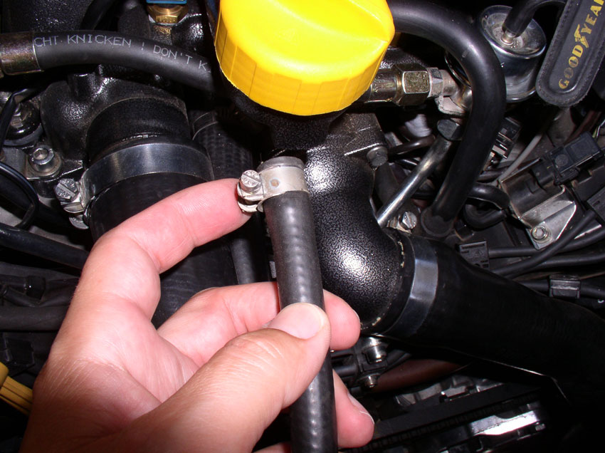
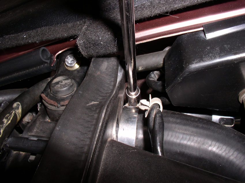
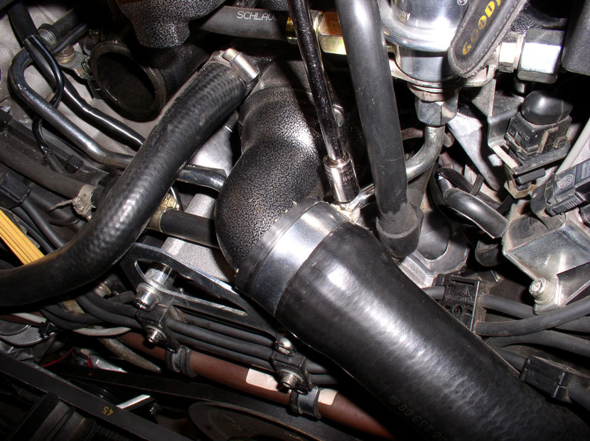
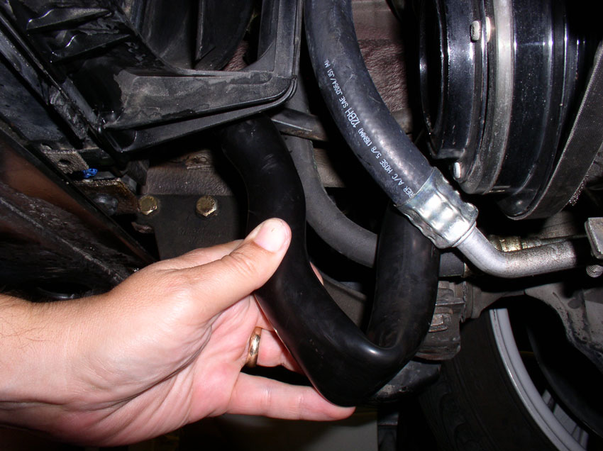
Next, remove the lower radiator hose. Loosen the clamp at the thermostat housing and remove the hose from the elbow pipe.
Then, from underneath, loosen the clamp at the radiator (assuming your clamp is facing downward. If not, you may have to access it from above.
Have your catch can ready in case there is residual coolant in the hose when you take it off. Remove the lower radiator hose and set it aside.
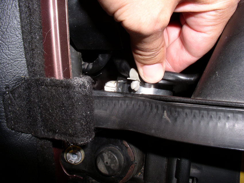
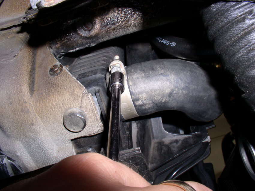
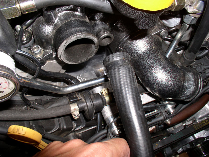
Lastly, remove the heater return hose from the thermostat housing.
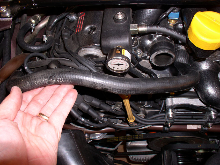
I used a long flat blade screwdriver to loosen the clamp as shown.
Pull the hose from the thermostat housing. There is almost always coolant left in this hose so have your catch can ready when you pull it off. Then point it downward (between the fan and engine) so the coolant can drain out into your catch can. Then set the hose out of the way. There is no need to disconnect the hose at the other end.
Continued.....
Then, from underneath, loosen the clamp at the radiator (assuming your clamp is facing downward. If not, you may have to access it from above.
Have your catch can ready in case there is residual coolant in the hose when you take it off. Remove the lower radiator hose and set it aside.
Lastly, remove the heater return hose from the thermostat housing.
I used a long flat blade screwdriver to loosen the clamp as shown.
Pull the hose from the thermostat housing. There is almost always coolant left in this hose so have your catch can ready when you pull it off. Then point it downward (between the fan and engine) so the coolant can drain out into your catch can. Then set the hose out of the way. There is no need to disconnect the hose at the other end.
Continued.....
01-01-2010, 04:35 PM
#7
Rennlist Member
Thread Starter
Join Date: Sep 2007
Location: Ridgecrest, California
Posts: 1,363
Likes: 0
Received 143 Likes
on
28 Posts
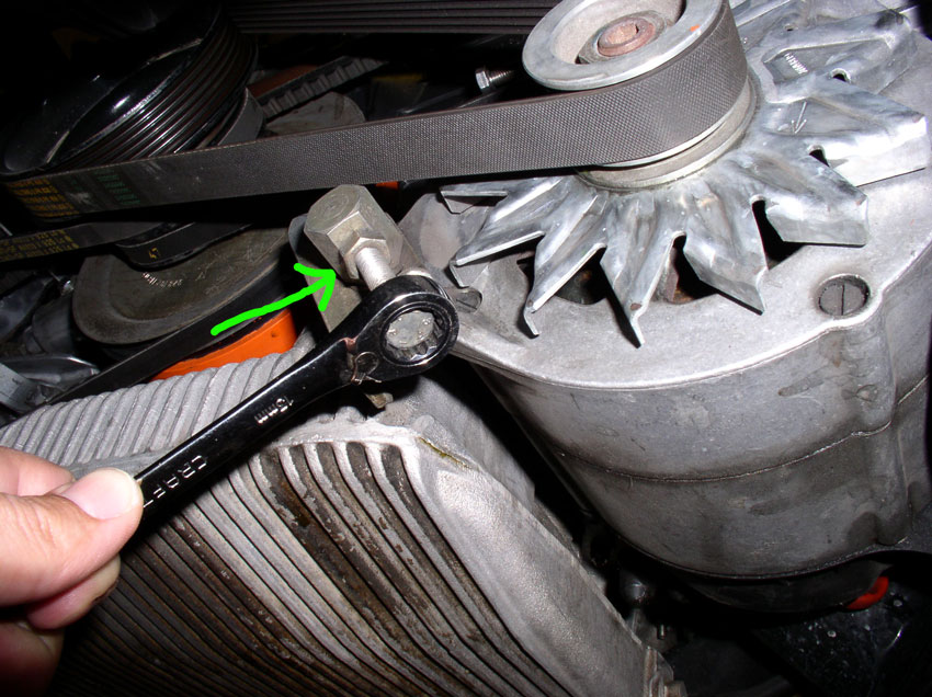
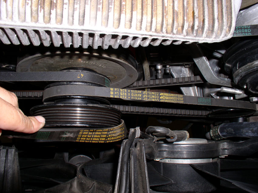
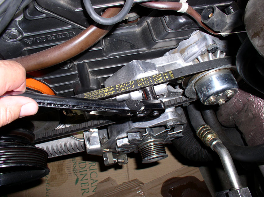
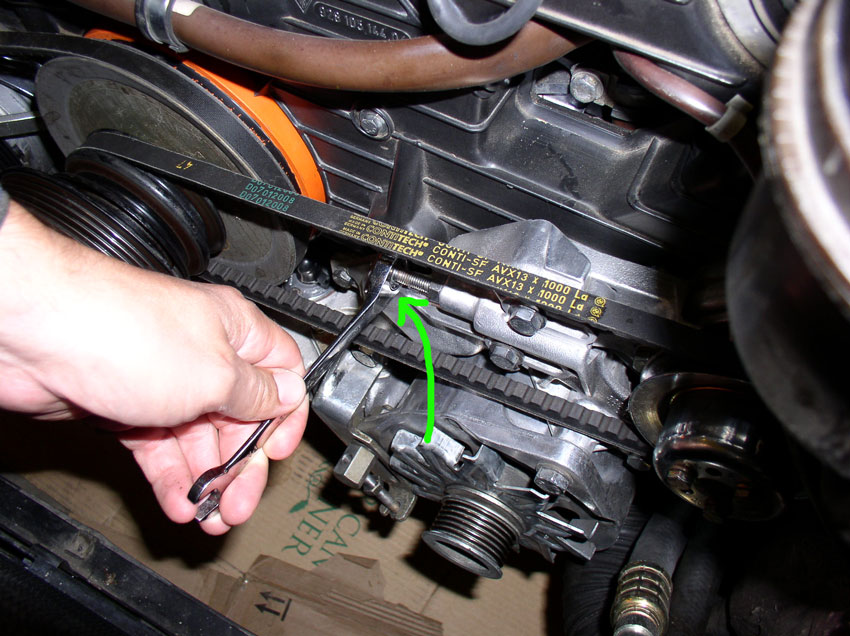
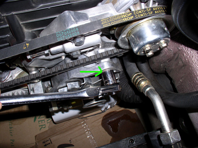
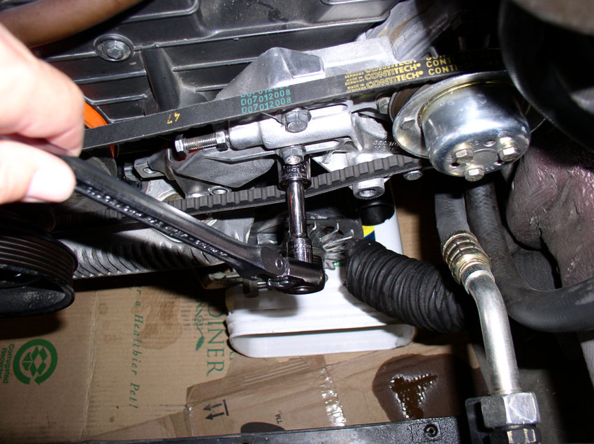
To remove the accessory belts, start with the outermost belt (alternator) and work toward the innermost belt (A/C). First, loosen the alternator pivot bolt as shown below. It's a 13mm bolt with M10 threads and 130mm in length. Do not remove the bolt yet.
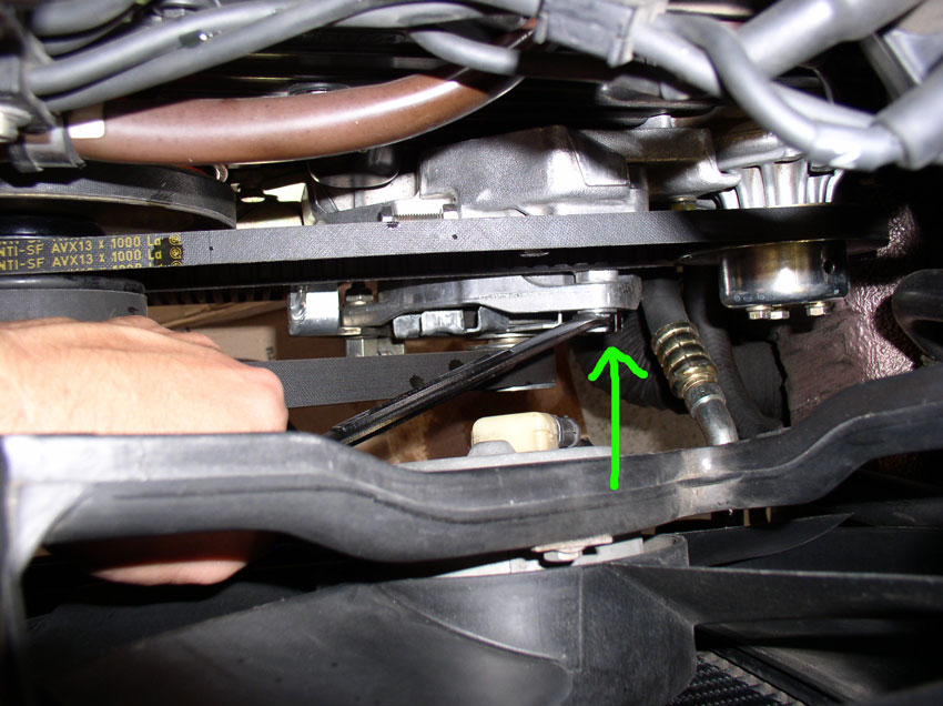
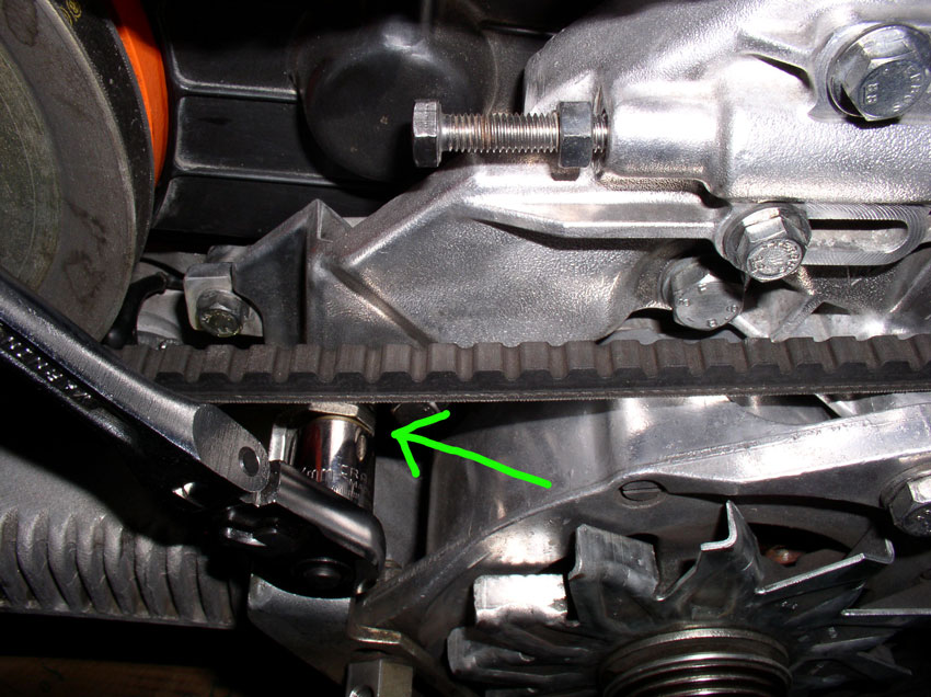
Next, from underneath, loosen the adjustment bolt locking nut (as indicated by the arrow), then begin loosening the adjuster bolt. Both take a 13mm wrench.
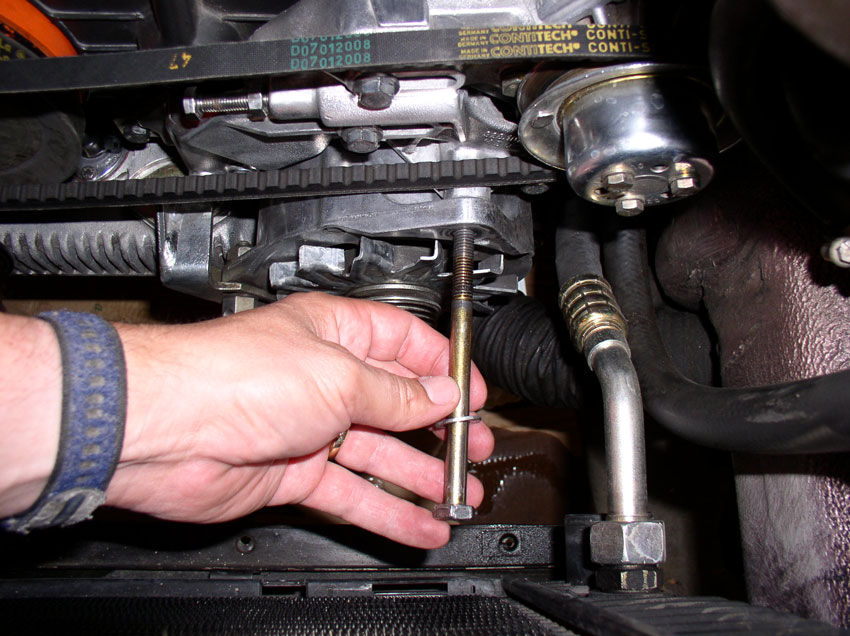
Continue to loosen the adjuster nut until you have slack in the belt as shown.
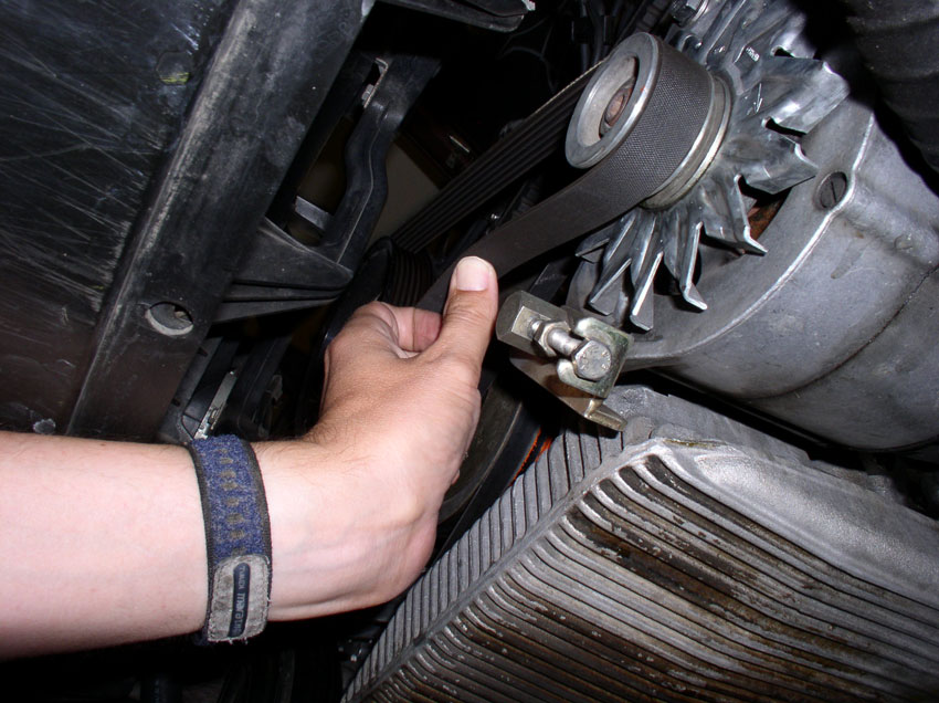
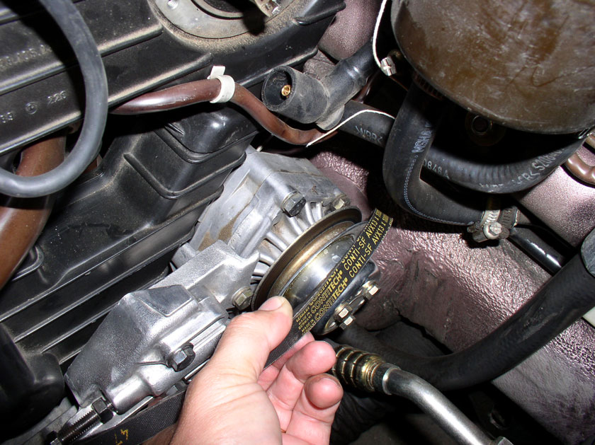
When you have enough slack in the belt, remove it from the pulleys.
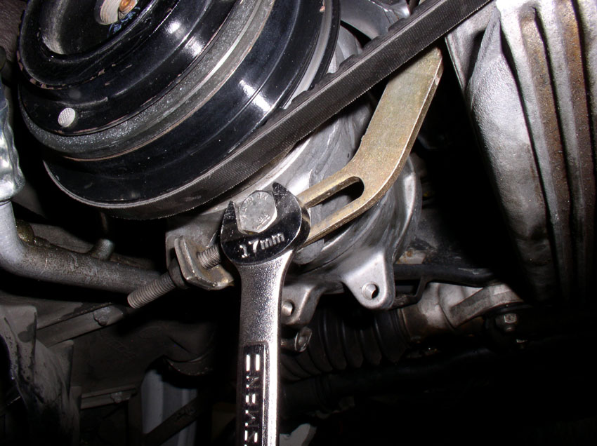
Next, remove the air pump belt. However, before I could remove the air pump belt, I needed to loosen the A/C compressor so I could move it out of the way then I could adjust the air pump enough to remove the belt. To loosen the A/C compressor, start by loosening the rear pivot bolt. The rear bolt is an M10 thread and 45mm in length. The bolt head, IIRC was 17mm.
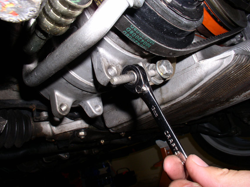
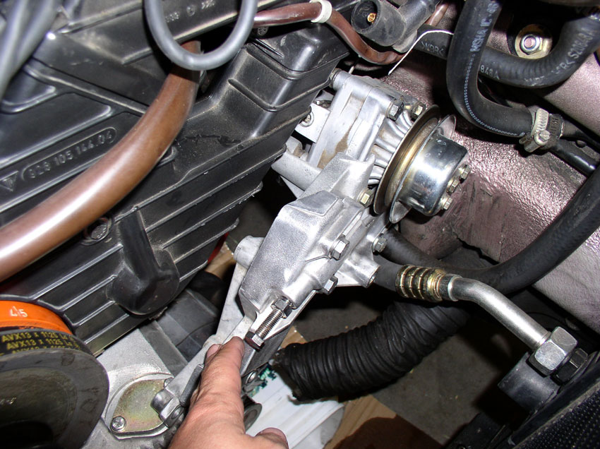
Then, loosen the front pivot bolt. This bolt is also M10 and 33mm long. It takes a 17mm wrench to loosen.
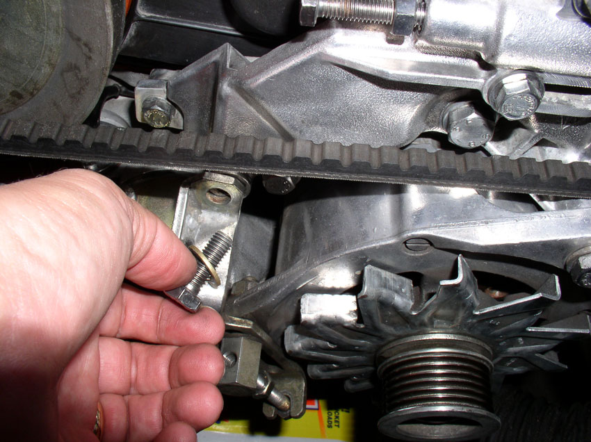
Next, loosen and remove the bolt for the support bracket for air pump and A/C compressor. We'll be removing the air pump later when working on the timing belt tensioner. It takes a 13mm socket as shown.
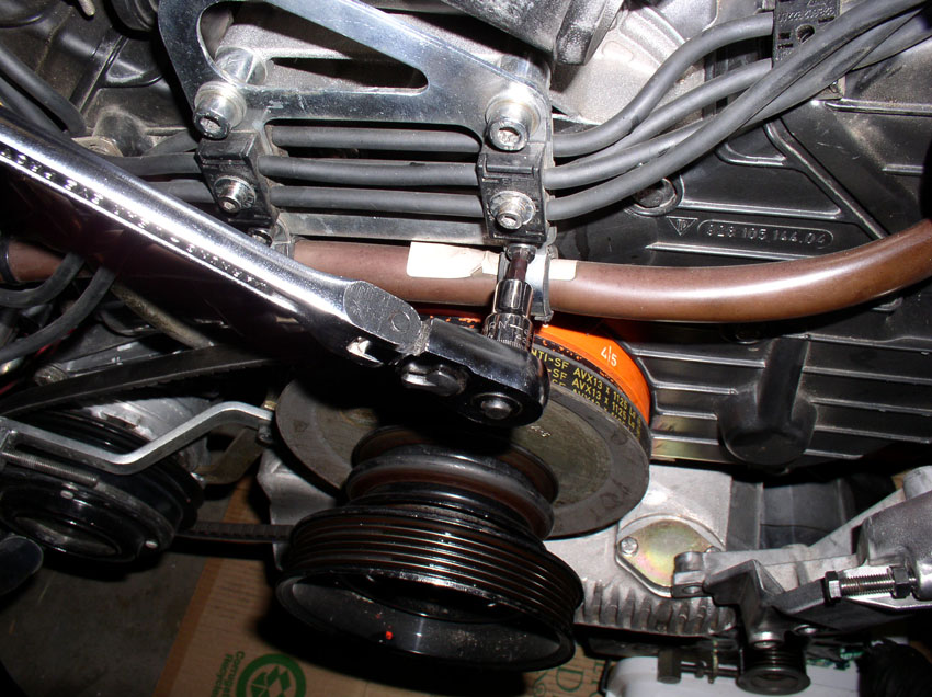
Loosen the compressor locking bolt using a 17mm wrench as shown.
Then, loosen the position adjustment nut for the A/C compressor using a 13mm wrench. Loosen the nut enough so you can move the compressor as far as possible in the belt-loosening direction.
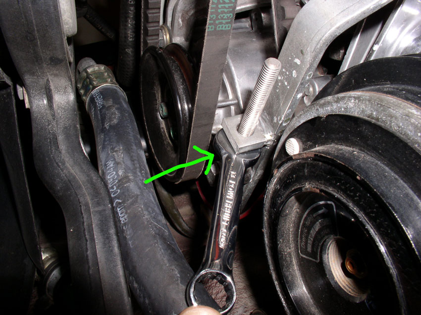
Now, loosen the Air Pump pivot bolt. It takes a 13mm wrench as shown.
Loosen the Air Pump locking bolt. It takes a 13mm wrench as shown.
Then, using a stubby 13mm wrench, loosen the adjustment nut as much as is needed to provide enough slack in the belt to remove it.
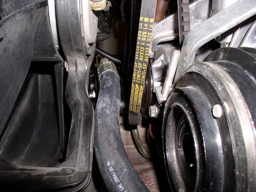
When you have enough slack, remove the belt.
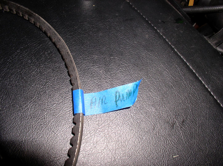
Mark the belt as to which accessory it came from. Air Pump in this case. The remaining two belts (Power Steering and A/C) will be removed when we remove the crank pulleys.
Continued......
Next, from underneath, loosen the adjustment bolt locking nut (as indicated by the arrow), then begin loosening the adjuster bolt. Both take a 13mm wrench.
Continue to loosen the adjuster nut until you have slack in the belt as shown.
When you have enough slack in the belt, remove it from the pulleys.
Next, remove the air pump belt. However, before I could remove the air pump belt, I needed to loosen the A/C compressor so I could move it out of the way then I could adjust the air pump enough to remove the belt. To loosen the A/C compressor, start by loosening the rear pivot bolt. The rear bolt is an M10 thread and 45mm in length. The bolt head, IIRC was 17mm.
Then, loosen the front pivot bolt. This bolt is also M10 and 33mm long. It takes a 17mm wrench to loosen.
Next, loosen and remove the bolt for the support bracket for air pump and A/C compressor. We'll be removing the air pump later when working on the timing belt tensioner. It takes a 13mm socket as shown.
Loosen the compressor locking bolt using a 17mm wrench as shown.
Then, loosen the position adjustment nut for the A/C compressor using a 13mm wrench. Loosen the nut enough so you can move the compressor as far as possible in the belt-loosening direction.
Now, loosen the Air Pump pivot bolt. It takes a 13mm wrench as shown.
Loosen the Air Pump locking bolt. It takes a 13mm wrench as shown.
Then, using a stubby 13mm wrench, loosen the adjustment nut as much as is needed to provide enough slack in the belt to remove it.
When you have enough slack, remove the belt.
Mark the belt as to which accessory it came from. Air Pump in this case. The remaining two belts (Power Steering and A/C) will be removed when we remove the crank pulleys.
Continued......
Trending Topics
01-01-2010, 04:41 PM
#8
Track Day

Join Date: Jan 2009
Location: Clarksville, TN
Posts: 15
Likes: 0
Received 0 Likes
on
0 Posts
Before you even finish this I want to say thank you. I'm new here and at this and I am currently trying to do all the research I can for timing belt replacement in my 86. I just purchased a manual made by someone from this forum and was just getting started reading it. I love the pics the ones in the manual I purchased are good but in black and white.
Honestly thank you, you dont know how valuable this is to me right now (well in a week or two). Keep with the "newbie related" theme...
Honestly thank you, you dont know how valuable this is to me right now (well in a week or two). Keep with the "newbie related" theme...
01-01-2010, 05:00 PM
#9
Rennlist Member
Thread Starter
Join Date: Sep 2007
Location: Ridgecrest, California
Posts: 1,363
Likes: 0
Received 143 Likes
on
28 Posts
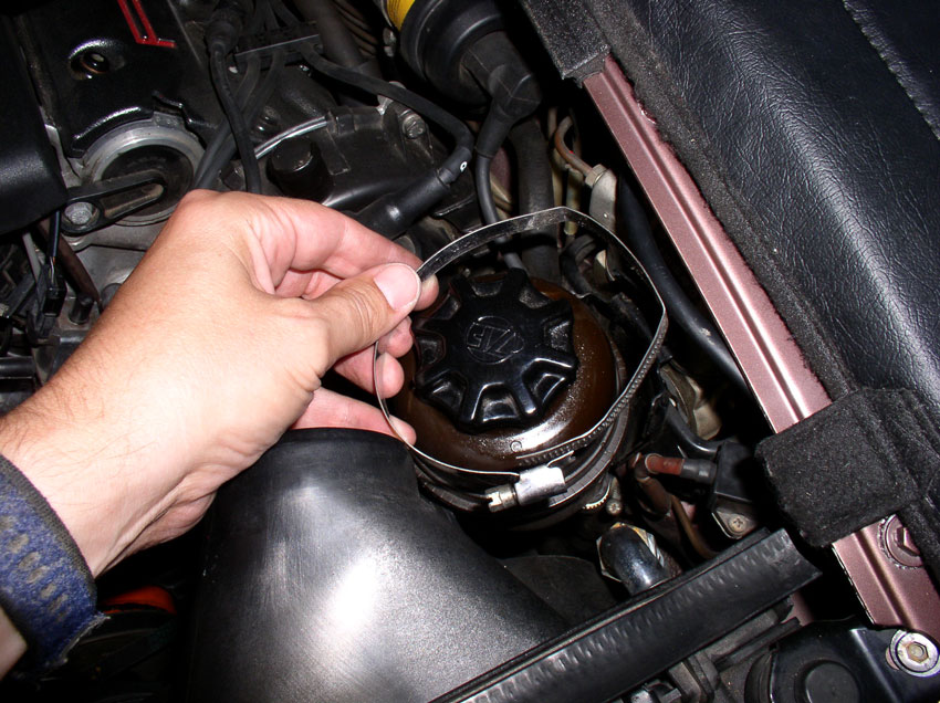
The fan shroud is a tight fit to get out so a few things need to be moved in order to make room. First, loosen the clamp on the power steering reservoir...
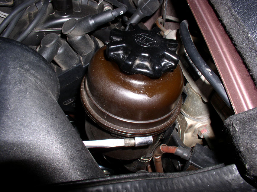
...and remove the clamp completely. The reservoir should stay upright by itself.
Then, remove the charging post nut cover.....
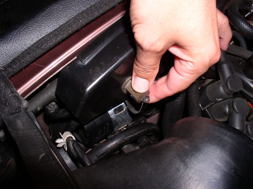
....and remove the plastic charging post cover.
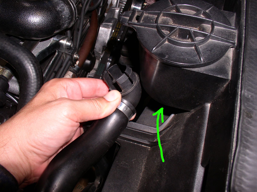
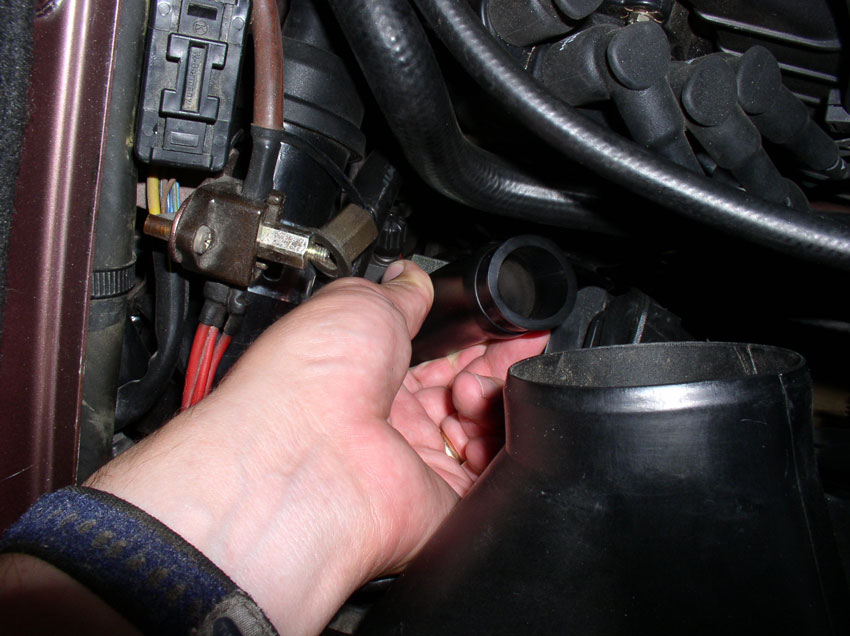
Remove the hose from the bottom of the air pump filter that's on top of the fan shroud. You can simply pull down on the plastic elbow to remove the elbow and hose from the filter housing.
Loosen the clamp and remove the plastic elbow from the hose. This is a precaution so the elbow won't get damaged during the next hose-contorting procedure.
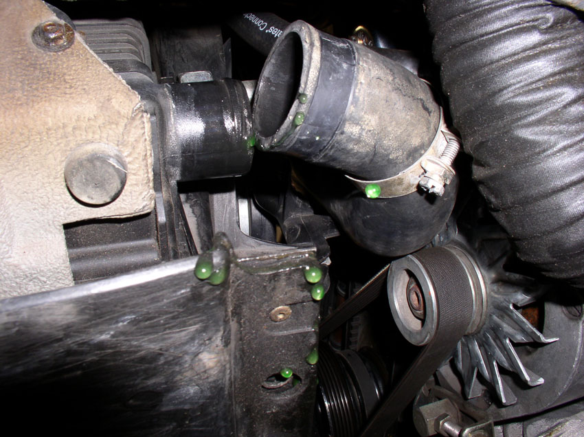
I found it easier to get the air pump hose out of the way while removing the fan shroud so I pushed it down between the fan shroud and engine as pictured.
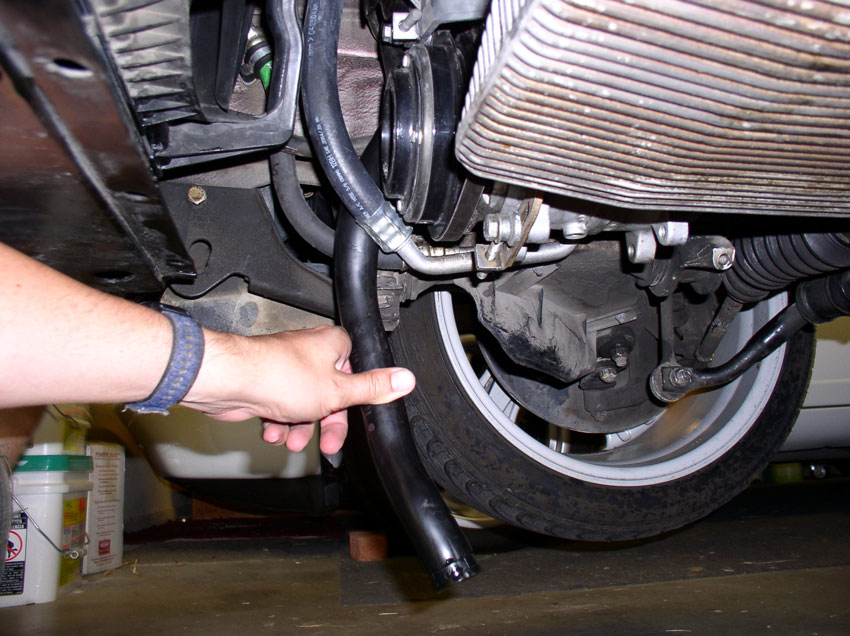
From underneath, you can continue to pull the air pump hose downward....
....Until the hose is pointing downward as shown.
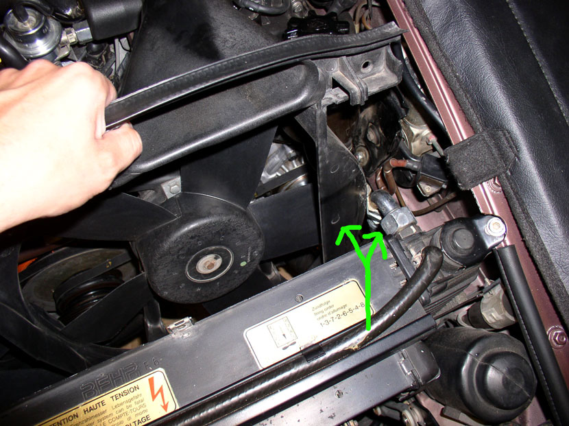
Next, remove the two 10mm screws that secure the top of the fan shroud to the top of the radiator.
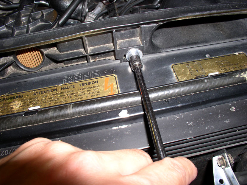
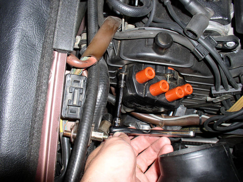
Although probably not neccessary to remove the fan shroud, I removed the distributor caps anyway since I would have to remove them later on. First, remove the spark plug wires from the distributor.
Then, remove the cap by completely loosening the 3 screws that secure the cap to the cam cover. I used a flat blade screwdriver on the top screw.
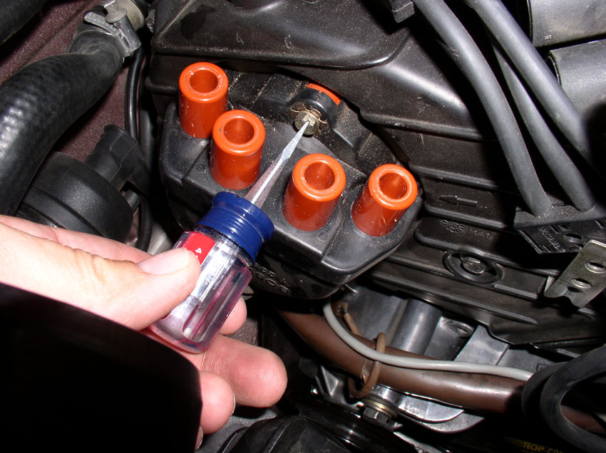
...and on the bottom right.
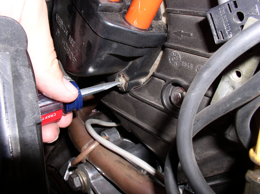
But I used a 8mm socket on the bottom left screw.
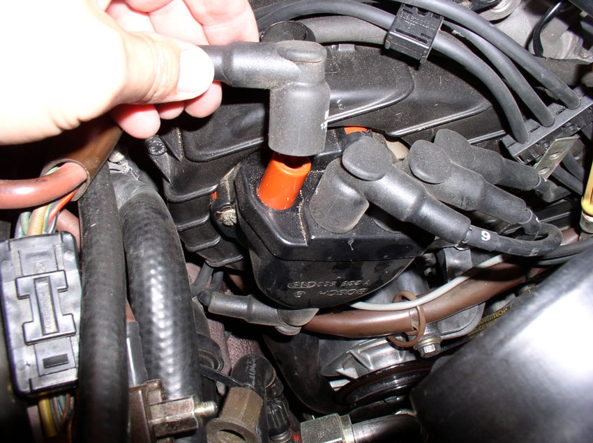
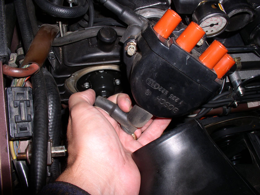
Once you have the cap off, remove the coil wire from the bottom of the cap.
Continued......
...and remove the clamp completely. The reservoir should stay upright by itself.
Then, remove the charging post nut cover.....
....and remove the plastic charging post cover.
Remove the hose from the bottom of the air pump filter that's on top of the fan shroud. You can simply pull down on the plastic elbow to remove the elbow and hose from the filter housing.
Loosen the clamp and remove the plastic elbow from the hose. This is a precaution so the elbow won't get damaged during the next hose-contorting procedure.
I found it easier to get the air pump hose out of the way while removing the fan shroud so I pushed it down between the fan shroud and engine as pictured.
From underneath, you can continue to pull the air pump hose downward....
....Until the hose is pointing downward as shown.
Next, remove the two 10mm screws that secure the top of the fan shroud to the top of the radiator.
Although probably not neccessary to remove the fan shroud, I removed the distributor caps anyway since I would have to remove them later on. First, remove the spark plug wires from the distributor.
Then, remove the cap by completely loosening the 3 screws that secure the cap to the cam cover. I used a flat blade screwdriver on the top screw.
...and on the bottom right.
But I used a 8mm socket on the bottom left screw.
Once you have the cap off, remove the coil wire from the bottom of the cap.
Continued......
01-01-2010, 05:24 PM
#10
Rennlist Member
Thread Starter
Join Date: Sep 2007
Location: Ridgecrest, California
Posts: 1,363
Likes: 0
Received 143 Likes
on
28 Posts
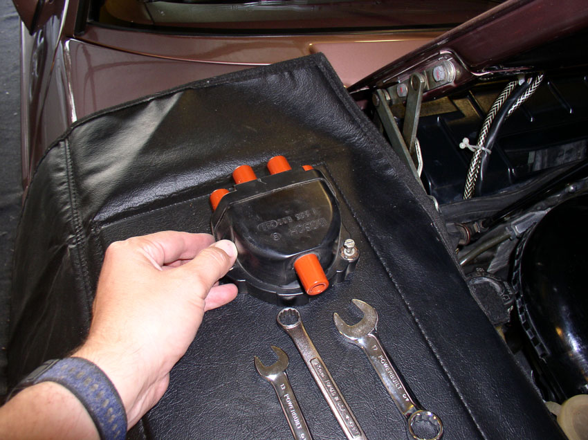
Set the distributor cap aside. I place it on the fender service cover corresponding to the side of the engine it came from. Perform the same operation on the distributor cap for the driver's side.
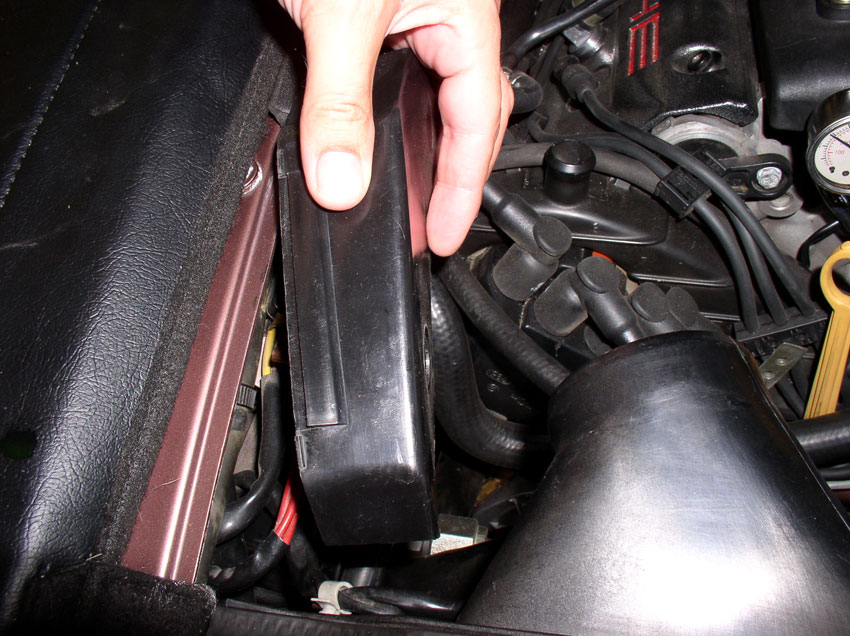
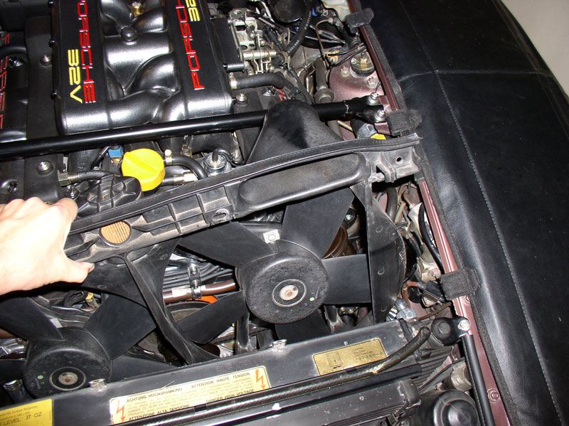
To remove the fan shroud, first pull the shroud up an inch or two - this should clear the two locking tabs on the front of the shroud.
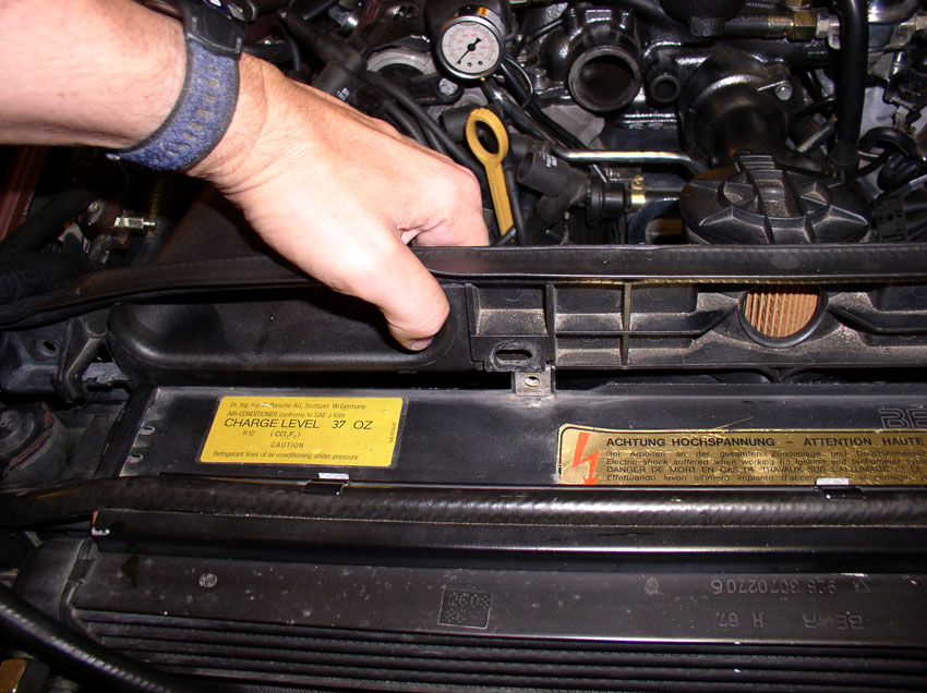
Then, push the right hand side of the shroud back enough to clear the top oil cooler line and nut as pictured below.
Next, pull up on the right hand side of the shroud enough to clear the obstacles on the right hand side of the engine bay. Then you should have enough room to pull the left hand side up and out.
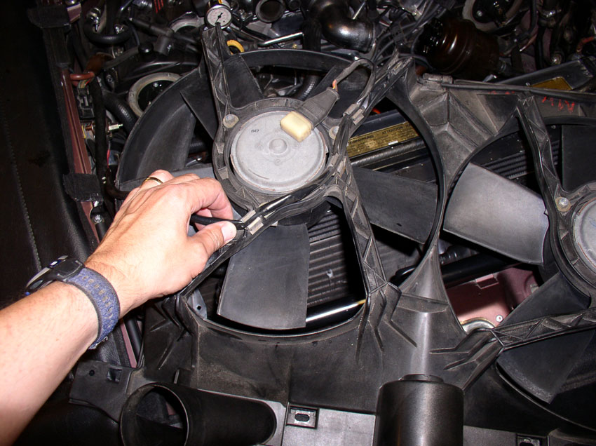
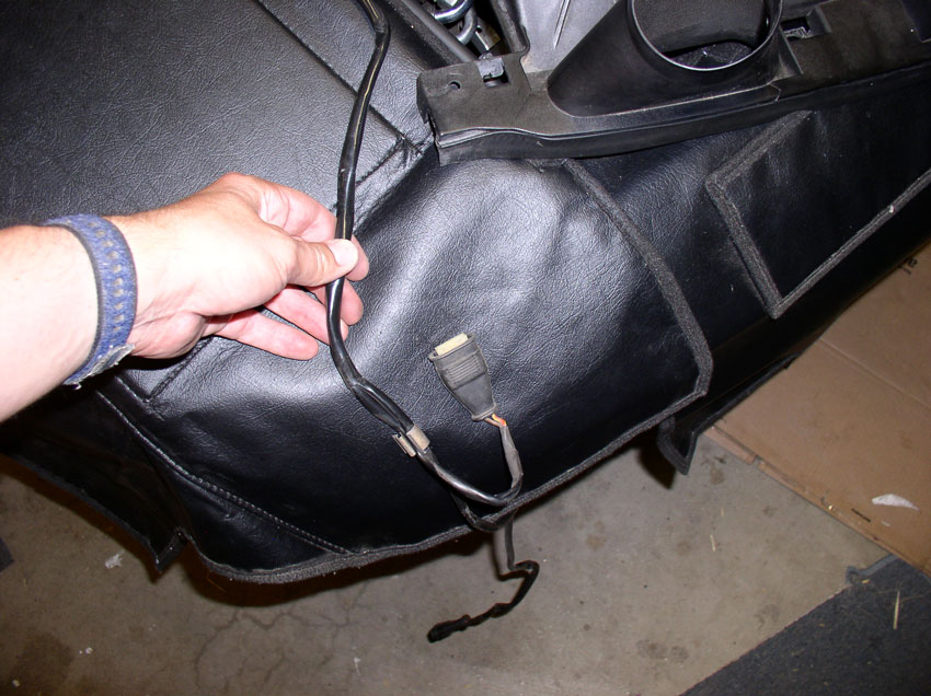
Lay the fan shroud face down (with backing exposed) across the top of the radiator as shown. Remove the wiring harness from the first few harness clips as shown.
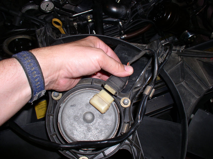
Pull both of the harness plugs from the fan motors.
Remove the wiring harness from the remaining harness clips as shown.
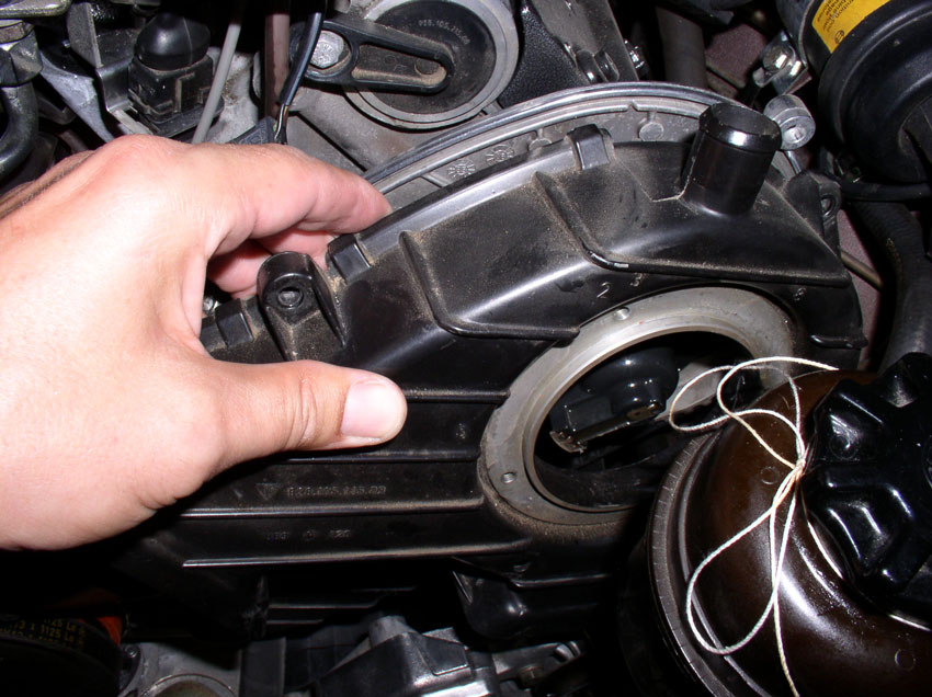
With the harness completely disconnected from the fan shroud, lay the harness aside and place the fan shroud out of the immediate work area.
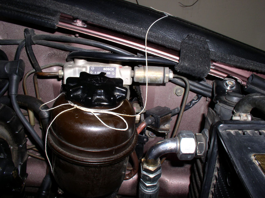
I then tied the PS reservoir with some string to keep it out of the way.
Continued......
To remove the fan shroud, first pull the shroud up an inch or two - this should clear the two locking tabs on the front of the shroud.
Then, push the right hand side of the shroud back enough to clear the top oil cooler line and nut as pictured below.
Next, pull up on the right hand side of the shroud enough to clear the obstacles on the right hand side of the engine bay. Then you should have enough room to pull the left hand side up and out.
Lay the fan shroud face down (with backing exposed) across the top of the radiator as shown. Remove the wiring harness from the first few harness clips as shown.
Pull both of the harness plugs from the fan motors.
Remove the wiring harness from the remaining harness clips as shown.
With the harness completely disconnected from the fan shroud, lay the harness aside and place the fan shroud out of the immediate work area.
I then tied the PS reservoir with some string to keep it out of the way.
Continued......
Last edited by Dwayne; 01-01-2010 at 07:02 PM.
01-01-2010, 06:21 PM
#11
Rennlist Member
Thread Starter
Join Date: Sep 2007
Location: Ridgecrest, California
Posts: 1,363
Likes: 0
Received 143 Likes
on
28 Posts
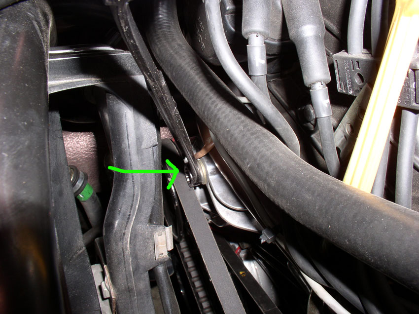
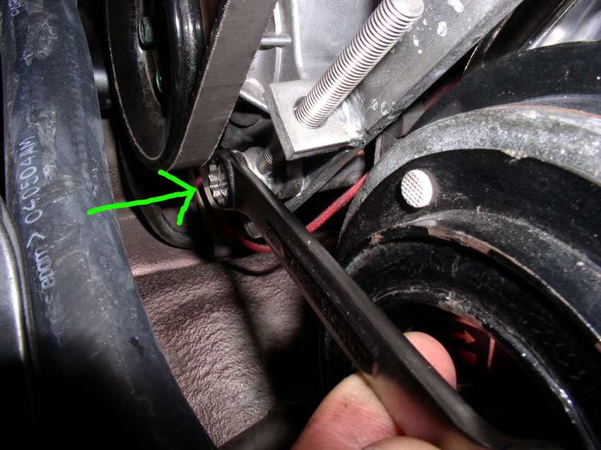
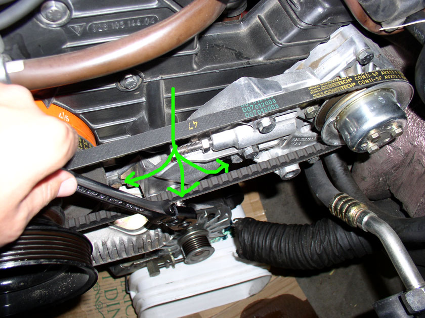
The Power Steering Pump belt tension is locked in place by the two 13mm bolts pointed at by the two green lines below. The pump is allowed to slide left or right toward minimum and maximum tension. The adjusting bolt is also locked in place by a locking nut pointed at by the green arrow below. First, loosen the lock nut. It takes a 13mm wrench.

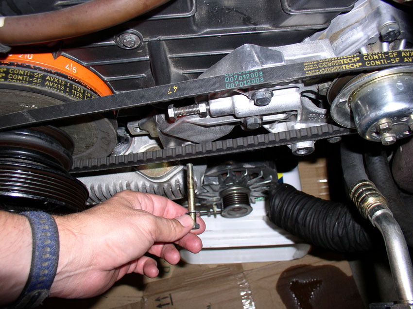
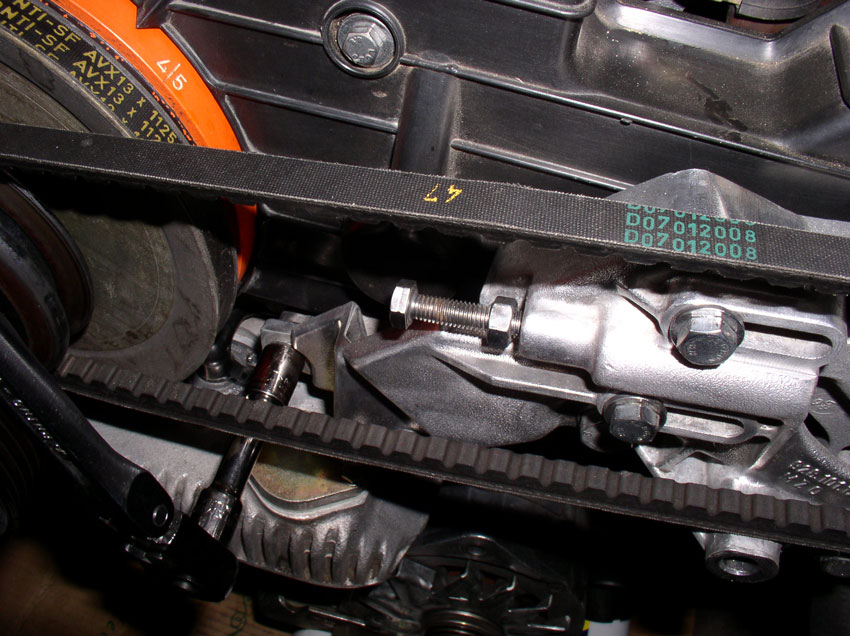
Loosen both of the sliding locking 13mm bolts as shown.
Then, using a 13mm wrench, loosen the belt tension adjustment bolt enough for the PS pump to slide all the way back to the loosest position.
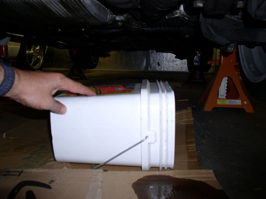
Next, we'll remove the alternator before removing the PS pump. Place a suitable container or box under the alternator so it can rest when removed without putting tension on the wiring harness. I used a plastic laundry soap container.
Loosen the alternator tension bracket bolt. It takes a 17mm socket and is a M10 X 25mm bolt.
Remove the bracket bolt as shown.
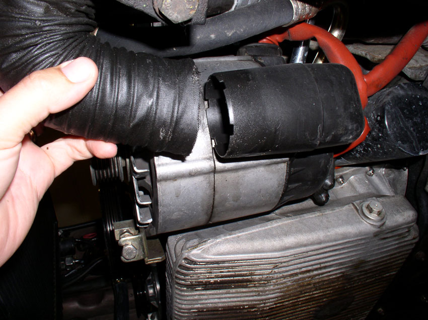
Remove the alternator cooling hose from the alternator air guide as shown.
Loosen the 17mm alternator pivot bolt....
....and remove the bolt completely. It is an M10 X 130mm bolt.
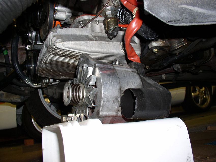
When you remove the pivot bolt, work the alternator back and forth to dislodge it from the mounting bracket. Then lay the alternator on top of the container as shown.
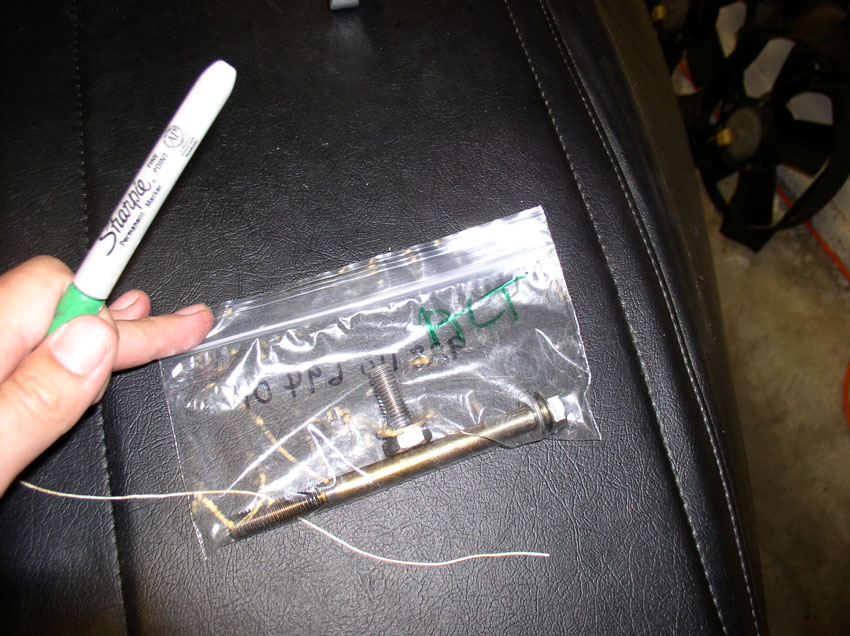
It's a good idea to bag and tag the bolts and nuts once removed. I use a plastic zip-lock baggie for parts and mark the bag accordingly. That way, bolts that look similar won't get misused.
The PS Pump mounting bracket is secured to the block using 3 bolts as indicated by the arrows in the picture. The left most bolt and middle bolt are 13mm bolts and the one on the right is a 17mm bolt.
The middle bolt is longer than the others.
Remove the left 13mm bolt.
Remove the 17mm bolt next.
Continued.....
Loosen both of the sliding locking 13mm bolts as shown.
Then, using a 13mm wrench, loosen the belt tension adjustment bolt enough for the PS pump to slide all the way back to the loosest position.
Next, we'll remove the alternator before removing the PS pump. Place a suitable container or box under the alternator so it can rest when removed without putting tension on the wiring harness. I used a plastic laundry soap container.
Loosen the alternator tension bracket bolt. It takes a 17mm socket and is a M10 X 25mm bolt.
Remove the bracket bolt as shown.
Remove the alternator cooling hose from the alternator air guide as shown.
Loosen the 17mm alternator pivot bolt....
....and remove the bolt completely. It is an M10 X 130mm bolt.
When you remove the pivot bolt, work the alternator back and forth to dislodge it from the mounting bracket. Then lay the alternator on top of the container as shown.
It's a good idea to bag and tag the bolts and nuts once removed. I use a plastic zip-lock baggie for parts and mark the bag accordingly. That way, bolts that look similar won't get misused.
The PS Pump mounting bracket is secured to the block using 3 bolts as indicated by the arrows in the picture. The left most bolt and middle bolt are 13mm bolts and the one on the right is a 17mm bolt.
The middle bolt is longer than the others.
Remove the left 13mm bolt.
Remove the 17mm bolt next.
Continued.....
01-01-2010, 06:29 PM
#12
Rennlist Member
Thread Starter
Join Date: Sep 2007
Location: Ridgecrest, California
Posts: 1,363
Likes: 0
Received 143 Likes
on
28 Posts
After removing the 3 PS bracket securing bolts, you can pull the PS bracket away from the block and easily remove the belt (and mark it).
Then turn the PS bracket away from the cam cover as shown in the picture. In this position, it provides enough clearance to get the center cam cover off.
Continued....
Then turn the PS bracket away from the cam cover as shown in the picture. In this position, it provides enough clearance to get the center cam cover off.
Continued....
01-01-2010, 06:58 PM
#13
Rennlist Member
Thread Starter
Join Date: Sep 2007
Location: Ridgecrest, California
Posts: 1,363
Likes: 0
Received 143 Likes
on
28 Posts
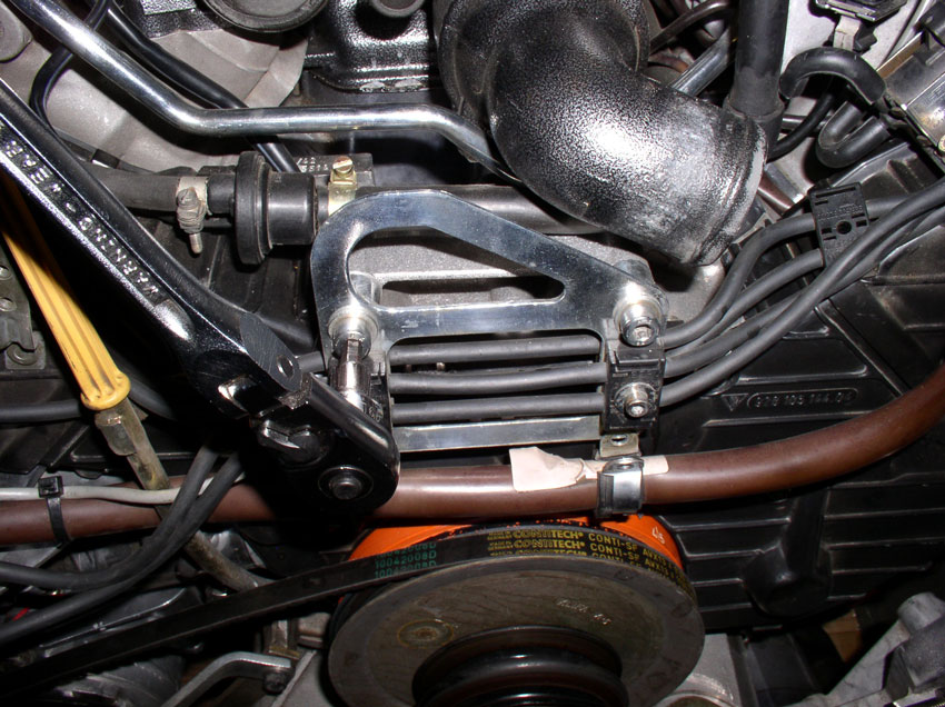
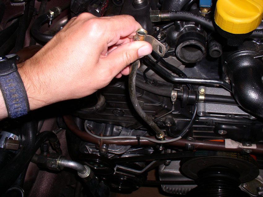
Disconnect the engine wiring harness from the center engine lift bracket using a 5mm allen head socket to loosen and remove the 2 harness clamps.
Then remove the engine lift bracket from the water pump housing by loosening and removing both of the 6mm allen head bolts as shown.
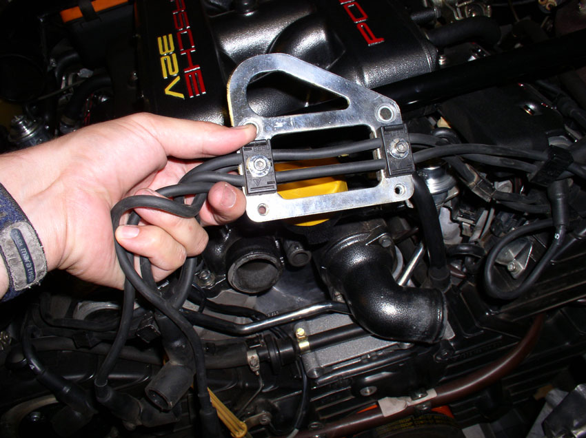
Lift the bracket up and over the oil filler neck out of the way.
Remove the oil dipstick from its tube.
Loosen and remove the 10mm bolt that secures the oil dipstick tube to the cam cover.
Remove the oil dipstick tube by lifting up and twisting slightly. The tube has an o-ring that seals the hole in the oil pan. If it doesn't come out with the tube, fish it out and place it on the tube or installation later. If the o-ring looks worn or damaged, order a replacement o-ring from one of the 928 vendors. Make sure to plug the dipstick tube hole in the oil pan with a towel or small rag to prevent debris from entering the oil pan.
Insert the dipstick back into the tube and set aside.
There are two 10mm bolts that hold the passenger side cam cover on. Remove the upper left bolt as shown below.
Then loosen and remove the 2nd middle bolt as shown....
....the 2nd bolt is the longer of the two.
Remove the cam cover by lifting slightly up and out so the lip on the cam cover clears the rear cam cover plate.
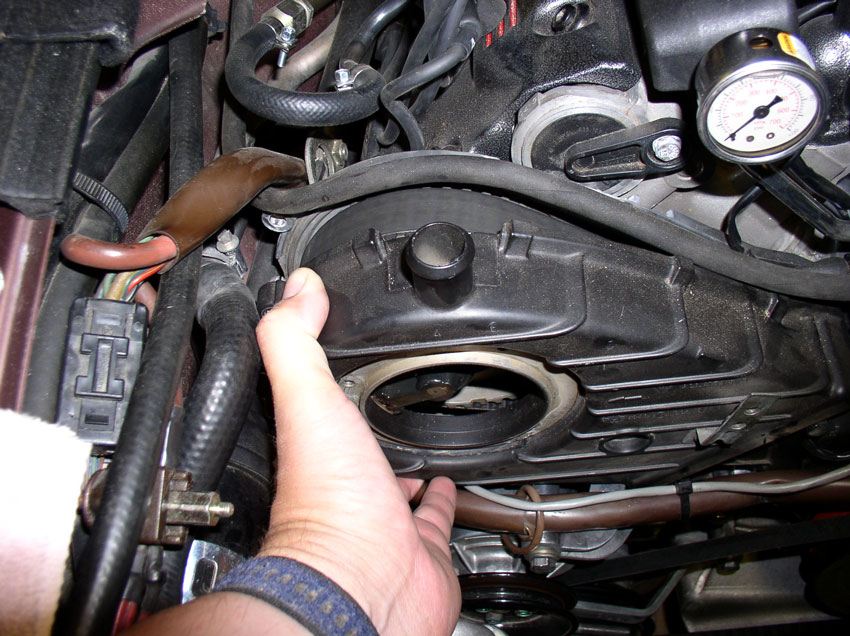
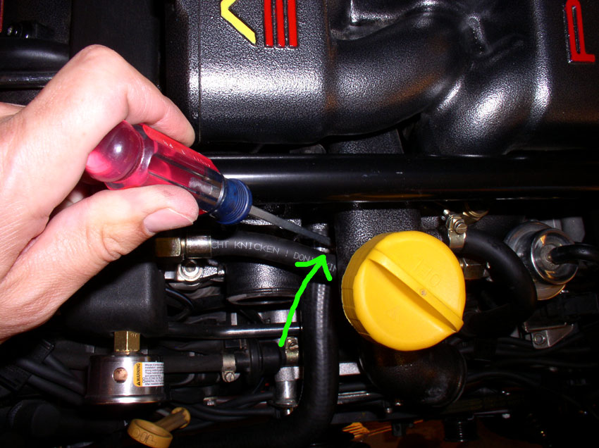
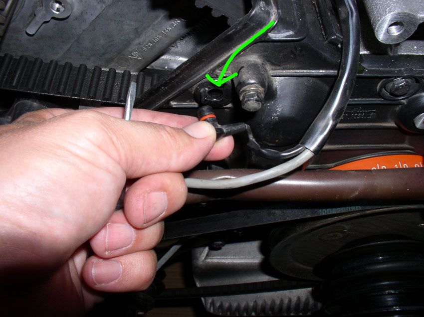
Lift the fuel vapor solenoid hose up and out of the way as shown.
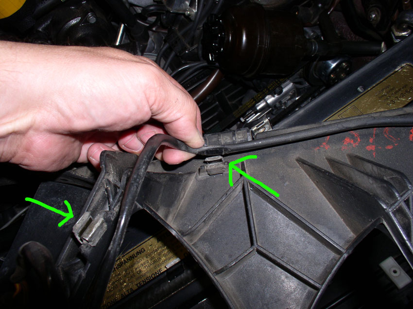
Carefully pry the locking plastic tab away from the belt tension warning wiring harness plug....
....and pull the wiring harness out of the plug as shown.
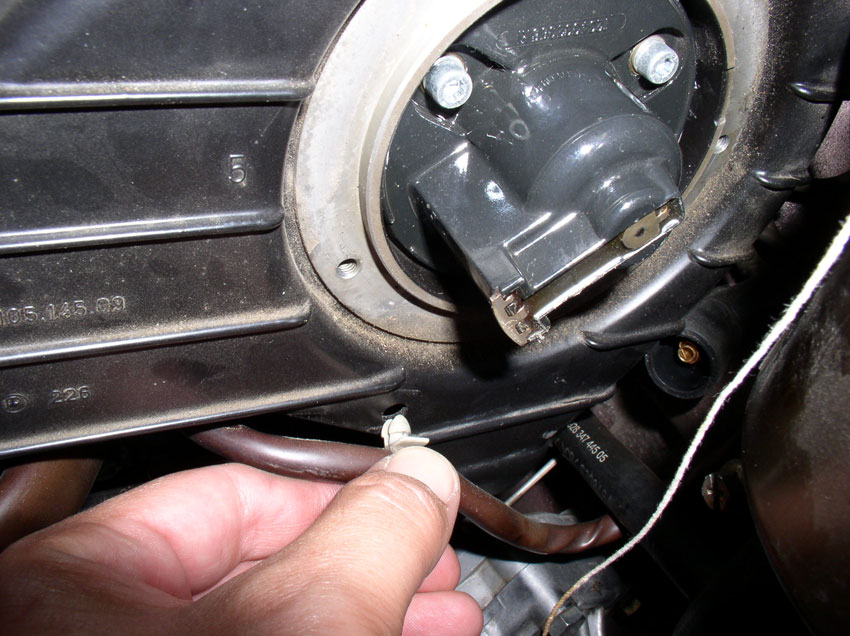
Remove the wiring harness clip from the driver's side cam cover as shown.
Continued......
Then remove the engine lift bracket from the water pump housing by loosening and removing both of the 6mm allen head bolts as shown.
Lift the bracket up and over the oil filler neck out of the way.
Remove the oil dipstick from its tube.
Loosen and remove the 10mm bolt that secures the oil dipstick tube to the cam cover.
Remove the oil dipstick tube by lifting up and twisting slightly. The tube has an o-ring that seals the hole in the oil pan. If it doesn't come out with the tube, fish it out and place it on the tube or installation later. If the o-ring looks worn or damaged, order a replacement o-ring from one of the 928 vendors. Make sure to plug the dipstick tube hole in the oil pan with a towel or small rag to prevent debris from entering the oil pan.
Insert the dipstick back into the tube and set aside.
There are two 10mm bolts that hold the passenger side cam cover on. Remove the upper left bolt as shown below.
Then loosen and remove the 2nd middle bolt as shown....
....the 2nd bolt is the longer of the two.
Remove the cam cover by lifting slightly up and out so the lip on the cam cover clears the rear cam cover plate.
Lift the fuel vapor solenoid hose up and out of the way as shown.
Carefully pry the locking plastic tab away from the belt tension warning wiring harness plug....
....and pull the wiring harness out of the plug as shown.
Remove the wiring harness clip from the driver's side cam cover as shown.
Continued......
Last edited by Dwayne; 01-03-2010 at 02:46 PM.
01-01-2010, 07:30 PM
#14
Addict
Rennlist Member
Rennlist Member
I will pay for this in a .pdf, I vote for Dwayne for 928 Man of the year 2010 and 2011, lol. Hey Dwayne my car is #356, they were both on the line at the same time. We should have a reunion one day. Too bad I'm flying to LA the end of Jan and not driving the car down. Cheers!
01-01-2010, 07:47 PM
#15
Rennlist Member
Thread Starter
Join Date: Sep 2007
Location: Ridgecrest, California
Posts: 1,363
Likes: 0
Received 143 Likes
on
28 Posts
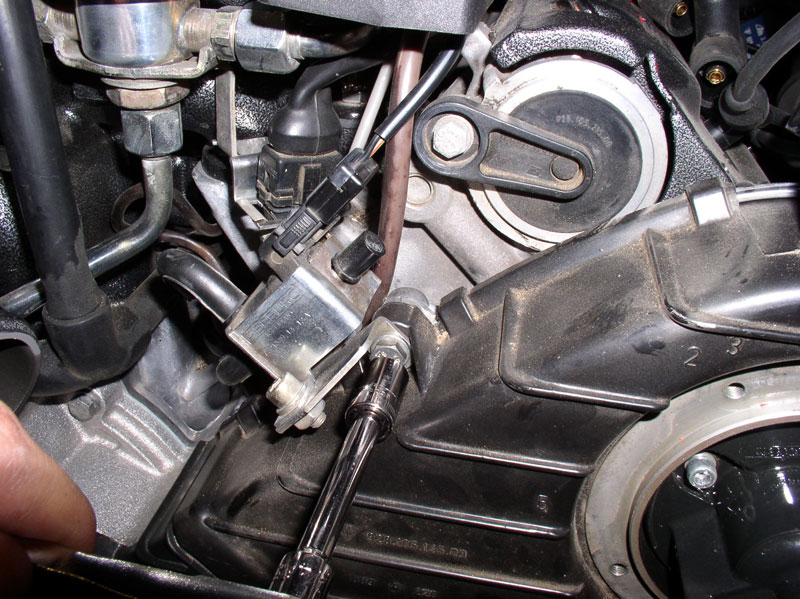
The driver's side cam cover is held in place by three 10mm bolts. Remove the first one that is left and top of the driver's side cam cover and also secures the flappy valve vacuum solenoid bracket as shown in the pic below.
Remove the uppermost 10mm bolt next as shown.
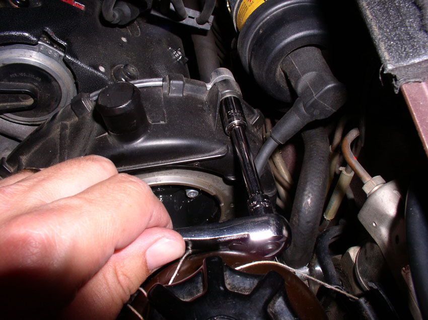
The third 10mm bolt is located out of sight in the opening for the engine harness. Locate and remove the bolt as shown in the pic below.
Now you should be able to remove the driver's side cam cover.
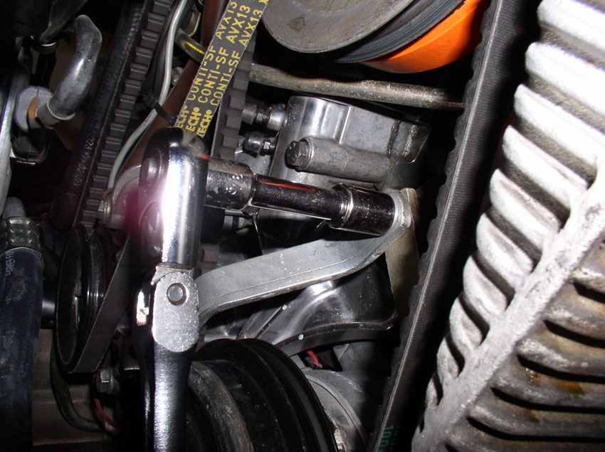
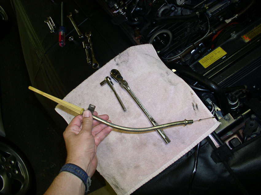
Now you will turn the engine to Top Dead Center (TDC) and check belt tightness and alignment of cam gear timing marks. I use a tall 27mm 6-point socket....
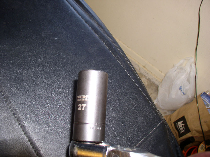
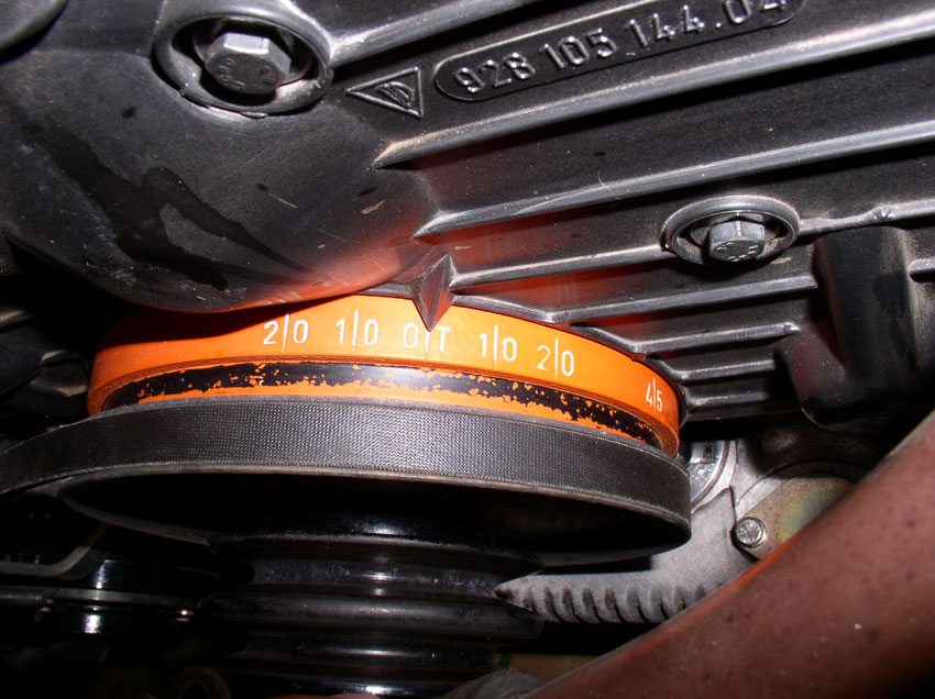
....and a long handle socket wrench to engage the crank bolt on the front of the engine as shown below. Turn the engine clockwise until.....
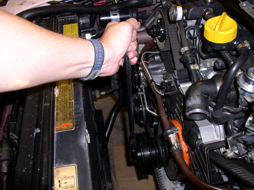
....the harmonic balancer is at TDC as shown below. Keep in mind that the crank turns 2 revolutions for every one revolution the cam gears make. Therefore, you need to also check the cam gears position to ensure the engine is really at TDC.
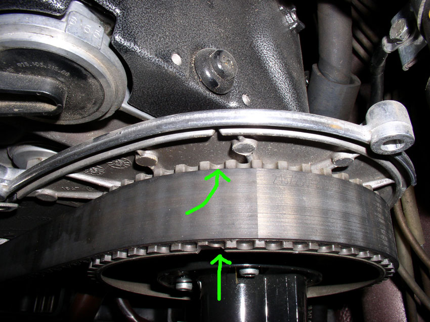
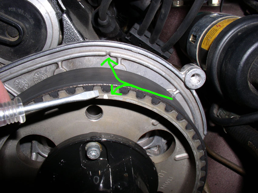
Check the cam gears when the harmonic balancer is at TDC. You should see a "V" notch cut into the metal cam cover back plate (shown opposite the top green arrow in the picture below). On the cam gear, you will also see a "V" notch cut into the back side of the cam gear pointed by the top green arrow (unfortunately, it does not show up well in this picture). There is also a notch cut in the front of the cam gear shown by the bottom arrow in the picture. These notches should line up very closely if not perfectly when the harmonic balancer is at TDC. If they are not, rotate the engine another revolution and the marks should line up.
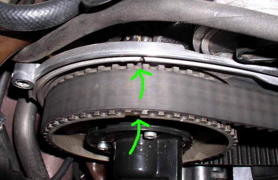
Both gears should line up the same or very close. Pictured here is the passenger side cam gear. When the balancer is at TDC, the driver's side gear is liined up perfectly but the passenger side gear is about 1/4 of a gear tooth off as you can see from tlhe photo.
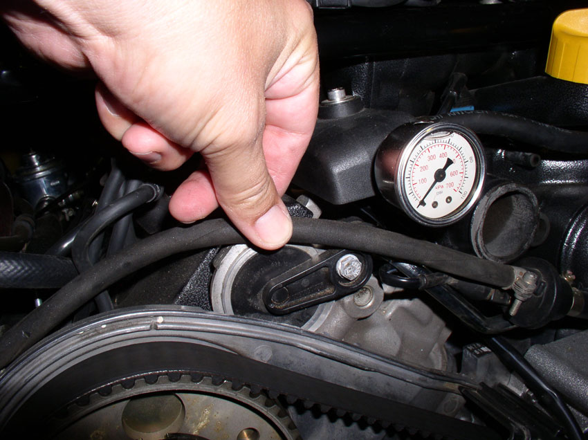
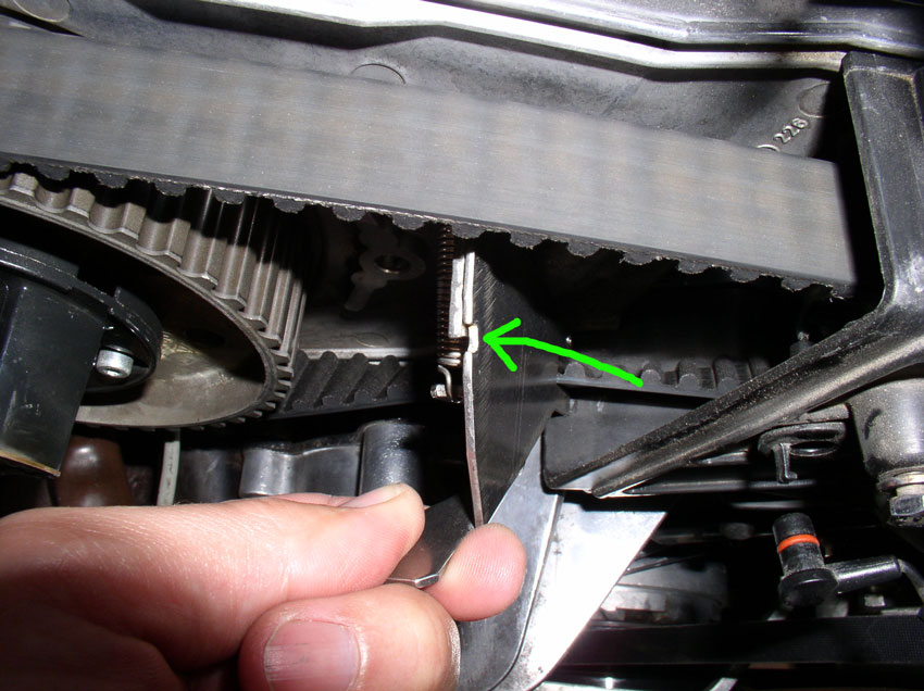
When the engine is at this position, you can check the belt tension. I checked the belt tension just for reference to know if it was running properly tensioned. I used the kempf tool to measure belt tension. Place the tool as close to the middle of the belt as you can get it (right in front of the timing belt center cover) and measure. You can see from this measurement the belt tension is in the middle of the tool notch - where it should be.
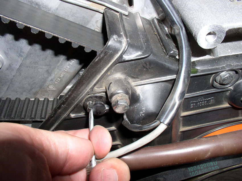
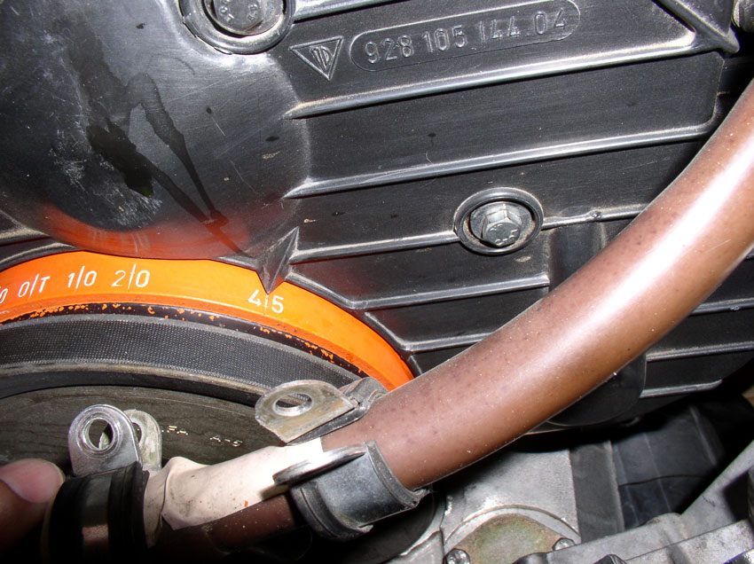
Now we need to set the crank at 45 degrees BTDC and lock the crank in place. In this 45 degree BTDC position, it is safe to work on the timing belt as none of the valves can contact the pistons if the cams move during the procedure. Move the crank clockwise 1 and 3/4 turns to the "45" mark as shown.
Using the "V" notch in the cam gear back plate, mark each timing gear with some paint as shown in the picture below. This is needed in case the gears move while the timing belt is off. With these marks, you will be able to line up the gears properly when installing the new belt. Mark both gears.
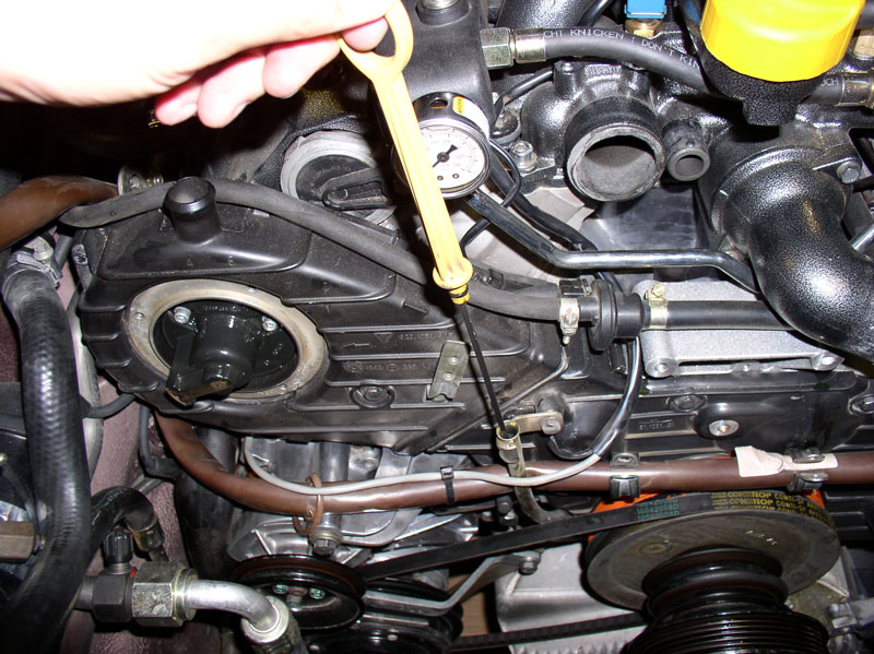
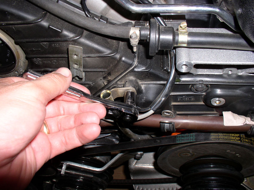
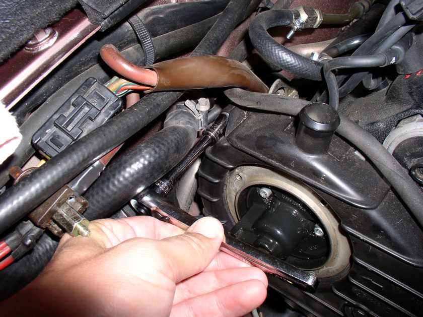
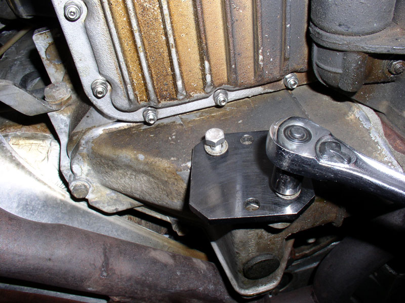
Go underneath the car and remove the flywheel inspection plate. The plate is secured with two 13mm bolts.
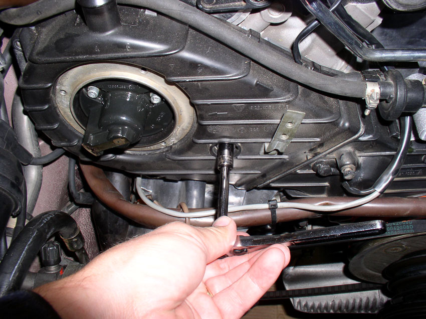
Insert the flywheel locking tool into the inpsection port and secure with two 13mm bolts.
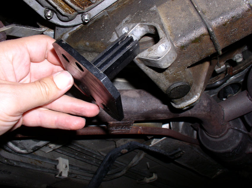
You will need longer bolts than the original 13mm bolts to secure the flywheel locking tool. I used 13mm bolts that were about 16mm-20mm in length. Now the engine crank is locked in place and we can remove the crank bolt and accessory pulleys.
Continued......
Remove the uppermost 10mm bolt next as shown.
The third 10mm bolt is located out of sight in the opening for the engine harness. Locate and remove the bolt as shown in the pic below.
Now you should be able to remove the driver's side cam cover.
Now you will turn the engine to Top Dead Center (TDC) and check belt tightness and alignment of cam gear timing marks. I use a tall 27mm 6-point socket....
....and a long handle socket wrench to engage the crank bolt on the front of the engine as shown below. Turn the engine clockwise until.....
....the harmonic balancer is at TDC as shown below. Keep in mind that the crank turns 2 revolutions for every one revolution the cam gears make. Therefore, you need to also check the cam gears position to ensure the engine is really at TDC.
Check the cam gears when the harmonic balancer is at TDC. You should see a "V" notch cut into the metal cam cover back plate (shown opposite the top green arrow in the picture below). On the cam gear, you will also see a "V" notch cut into the back side of the cam gear pointed by the top green arrow (unfortunately, it does not show up well in this picture). There is also a notch cut in the front of the cam gear shown by the bottom arrow in the picture. These notches should line up very closely if not perfectly when the harmonic balancer is at TDC. If they are not, rotate the engine another revolution and the marks should line up.
Both gears should line up the same or very close. Pictured here is the passenger side cam gear. When the balancer is at TDC, the driver's side gear is liined up perfectly but the passenger side gear is about 1/4 of a gear tooth off as you can see from tlhe photo.
When the engine is at this position, you can check the belt tension. I checked the belt tension just for reference to know if it was running properly tensioned. I used the kempf tool to measure belt tension. Place the tool as close to the middle of the belt as you can get it (right in front of the timing belt center cover) and measure. You can see from this measurement the belt tension is in the middle of the tool notch - where it should be.
Now we need to set the crank at 45 degrees BTDC and lock the crank in place. In this 45 degree BTDC position, it is safe to work on the timing belt as none of the valves can contact the pistons if the cams move during the procedure. Move the crank clockwise 1 and 3/4 turns to the "45" mark as shown.
Using the "V" notch in the cam gear back plate, mark each timing gear with some paint as shown in the picture below. This is needed in case the gears move while the timing belt is off. With these marks, you will be able to line up the gears properly when installing the new belt. Mark both gears.
Go underneath the car and remove the flywheel inspection plate. The plate is secured with two 13mm bolts.
Insert the flywheel locking tool into the inpsection port and secure with two 13mm bolts.
You will need longer bolts than the original 13mm bolts to secure the flywheel locking tool. I used 13mm bolts that were about 16mm-20mm in length. Now the engine crank is locked in place and we can remove the crank bolt and accessory pulleys.
Continued......