
Port and Polish by Comiittee thread (Cool pics throughout)
 01-26-2015, 02:19 PM
#271
Addict
Rennlist Member
Rennlist Member
Join Date: Feb 2004
Location: Monterey Peninsula, CA
Posts: 2,374
Likes: 0
Received 16 Likes
on
12 Posts
The V6 has crankshaft 240 degree pulse separation per bank. The 1-3-7-2-6-5-4-8 has 90-180-270-180 degree separation. This is obviously relevant. My view is that for a V8 such as ours, the secondary (or tertiary in 4-2-1) pipe that combines the 1-3 (and 5-6 on the other side) should be a little bit larger than the primary pipe and a little bit larger than the secondary pipe in a V6 bank. This is because the 90-degree pulses land largely on top of each other.
In contrast, I would make the argument that the primary pipes of the V8 should be even smaller than those in a V6. We've got one weapon to fight the reversal and blowdown interference, which is high velocity in the primary pipes. The main way of getting high velocity into those pipes is to keep the primary diameter small! (This is a theory, not a fact.) .
In contrast, I would make the argument that the primary pipes of the V8 should be even smaller than those in a V6. We've got one weapon to fight the reversal and blowdown interference, which is high velocity in the primary pipes. The main way of getting high velocity into those pipes is to keep the primary diameter small! (This is a theory, not a fact.) .
Other things to consider with the Audi 2.7 vs the 928 5.0 is the displacement per cylinder. The Audi is 450 cc and the Porsche is 625 cc. Depending on the camshaft and the port shape not to mention the valve size and angles you have a lot of variances.. ( better comparison would be like sized cylinders with varying exhaust port to get the true effect of just the port size variance)
As Ake mentioned, the design of the Audi motor as a turbocharged application for low end torque and fast spool up. In the N/A world it is different than the forced induction world.
One significant difference is camshaft, as it is not recommended to use high overlap cams in forced induction. While on high rpm N/A motors that is the preferred way to go.
On another note, you mentioned reversion. There are other simple tricks that can be used to fight reversion in the exhaust header, such as anti reversion tabs in the header at the head mating joint. Is does not necessarily mean the header has to be smaller.. It needs to be sized for the exhaust charge going through it.. (For example, if it were 2.7mm vs 27mm the velocity would be special, but the back pressure would then be astronomical..)
With all that said, the calculation should be made for the size of cylinder, the target power and torque curves, and then design the header to suit along with the rest of the exhaust pipe. This should also be done for the intake side of the engine.
Another point to consider is the BSFC of the motor, or what you will operate it at. The egt will also be different for different Lambda as well as the same, as the egt will peak and then lower as the lambda goes from rich to lean and too lean where detonation sets in. (Key is knowing which egt value is for rich and which for lean lambda, and where on the egt value curve you are on. In other words, are you before or after the egt peak)
The egt will have an effect on velocity, pressure and heat energy in the exhaust charge...
This will affect the way the turbines spool and in turn affect how the compressor affects the intake side of the engine..
Remember that formula in your toolbox that dictates the relationship between temperature and the air...?
As I mentioned previously, the part I ponder is the dynamic relationship of all those tiny bits in the engine model as functions over time..

Cheers
Sent from my iPhone using Rennlist
 01-26-2015, 03:34 PM
#272
Nordschleife Master
Whether or not turbo cars should have a lot of overlap or not depends on mainly three things.
First, firing order and separation of pulses. A lot of overlap doesn't work well with 180-degree exhaust blowdown interference at low rpms or 90-degree interference at high rpms.
Second, the static absolute pressure ratio between intake and exhaust that is needed to operate the turbo compressor. If we get the boost pressure above the static exhaust manifold pressure, overlap works well. Turbine geometry is important here.
Third, and related to the second point, exhaust gas velocity. The total pressure from the cylinder will convert to some combination of kinetic pressure and static pressure. Small exhaust ports and manifold pipes allow one to lower the static exhaust manifold pressure by making sure that as much of the cylinder pressure as possible is in the form of kinetic pressure. Both drive the turbine just fine, but only one hurts at overlap.
If you swap free-flowing turbos to the new Nissan GT-R, for example, I believe you can run wild cams and have the engine respond like a normally aspirated engine to camshaft overlap. The same situation with some turbo-Hayabusa bikes with high-quality turbo kits. (Turbobusas are true "donorcycles" but that's a matter for another day...)
I am not a fan of reversal steps or other anti-reversal mechanisms in the exhaust port or headers, bar one: high exhaust velocity! You probably guessed that! ;-) I am starting to sound like that MototuneUSA dude.
To combat reversion, I think that the exhaust header should be port matched to the exhaust port as long as the CSA's are appropriately small to keep the velocity up. I also think that making the header pipe smaller than the exhaust port (with smooth transition) helps combat reversion and making it larger than the exhaust port (even with a sharp step at the bottom) increases reversion -- for the simple reason that most exhaust ports are too large to start with. For an appropriately sized exhaust port, the best anti-reversion design is a header primary of the exact same ID as the exhaust port, with a step to a larger pipe size at about 8"-14" distance.
Goes without saying that this is just my theory and I don't have much experience with NA exhaust to speak of.
01-26-2015, 04:57 PM
#273
Rennlist Member
Thread Starter

Velocity is important, but like I think was mentioned above at some point, you can only go so far.
True blockage can occur when you transition from the primary to the collector. Smoothing or opening that collector seems to create power, but there is little proof online when it needs to be clinically separated from the data that results from the actual change from headers.
True blockage can occur when you transition from the primary to the collector. Smoothing or opening that collector seems to create power, but there is little proof online when it needs to be clinically separated from the data that results from the actual change from headers.
01-26-2015, 06:16 PM
#274
Nordschleife Master
For a high performance, high revving NA engine running wild cams with much overlap, you need fairly big header pipes. The diameter of the header pipe very much determine at what rpm peak torque will occur. The length more or less shift the power curve around that point.
The rule of thumb for a very high performance 427CI V8 engine having peak torque at about 6000 to 6500 rpm and putting out well above 700 HP, tells me the optimum header size is somewhere in the range 2 1/8" to 2 1/4" OD. Here is a test performed on a less (600 hp) powerful 427 CI engine. Best size is 2.0". http://www.hotrod.com/how-to/engine/...ers-dyno-test/
The rule of thumb for a very high performance 427CI V8 engine having peak torque at about 6000 to 6500 rpm and putting out well above 700 HP, tells me the optimum header size is somewhere in the range 2 1/8" to 2 1/4" OD. Here is a test performed on a less (600 hp) powerful 427 CI engine. Best size is 2.0". http://www.hotrod.com/how-to/engine/...ers-dyno-test/
You've tuned so many engines you would probably know the answer to that question off hand if we'd know the cam they used. Too bad Hotrod Magazine didn't even report the cam specs -- in a header test?!
Of course, there's a limit to anything, I am not talking about taking this to its (il)logical extreme. First potential problem is the following: If the velocity is high, at some point the fresh charge is just going down the exhaust tube, and not creating any power. Then we're just left with pumping losses. Second potential problem: It's also possible that at some point the pipe chokes so much that exhaust gas in the cylinder just compresses and doesn't exit or exits (undesirably) thru the intake port. I'd rate the first problem a more likely practical problem with our 4-valve heads, but what do I know.
Last edited by ptuomov; 01-26-2015 at 08:59 PM.
01-27-2015, 03:34 PM
#275
Rennlist Member
Join Date: Feb 2011
Location: Mostly in my workshop located in Sweden.
Posts: 2,226
Received 442 Likes
on
244 Posts
Tuomo, a few words about my thinking of how to size the exhaust port for the 427CI stroker. It is very simple same CSA for the port as for the ID at the valve seat rings (the throat).
Stock 928S4 head with 33mm exhaust valves: Exhaust port circular 40mm CSA 1257mm2. Throat 28,4mm combined CSA 1267mm2.
Race head with 36mm exhaust valves: Exhaust port oval 50 x 40mm CSA 1657mm2. Throat 32,4mm combined CSA 1648mm2.
2.125" header pipe ID 51mm CSA 2043mm2 will create a sufficient anti reversal step at the flange.
My test header flange can be viewed on post #257, second picture from the top.
�ke
01-27-2015, 04:50 PM
#276
Addict
Rennlist Member
Rennlist Member
Join Date: Feb 2004
Location: Monterey Peninsula, CA
Posts: 2,374
Likes: 0
Received 16 Likes
on
12 Posts
Whether or not turbo cars should have a lot of overlap or not depends on mainly three things.
First, firing order and separation of pulses. A lot of overlap doesn't work well with 180-degree exhaust blowdown interference at low rpms or 90-degree interference at high rpms.
Second, the static absolute pressure ratio between intake and exhaust that is needed to operate the turbo compressor. If we get the boost pressure above the static exhaust manifold pressure, overlap works well. Turbine geometry is important here.
Third, and related to the second point, exhaust gas velocity. The total pressure from the cylinder will convert to some combination of kinetic pressure and static pressure. Small exhaust ports and manifold pipes allow one to lower the static exhaust manifold pressure by making sure that as much of the cylinder pressure as possible is in the form of kinetic pressure. Both drive the turbine just fine, but only one hurts at overlap.
If you swap free-flowing turbos to the new Nissan GT-R, for example, I believe you can run wild cams and have the engine respond like a normally aspirated engine to camshaft overlap. The same situation with some turbo-Hayabusa bikes with high-quality turbo kits. (Turbobusas are true "donorcycles" but that's a matter for another day...)
I am not a fan of reversal steps or other anti-reversal mechanisms in the exhaust port or headers, bar one: high exhaust velocity! You probably guessed that! ;-) I am starting to sound like that MototuneUSA dude.
To combat reversion, I think that the exhaust header should be port matched to the exhaust port as long as the CSA's are appropriately small to keep the velocity up. I also think that making the header pipe smaller than the exhaust port (with smooth transition) helps combat reversion and making it larger than the exhaust port (even with a sharp step at the bottom) increases reversion -- for the simple reason that most exhaust ports are too large to start with. For an appropriately sized exhaust port, the best anti-reversion design is a header primary of the exact same ID as the exhaust port, with a step to a larger pipe size at about 8"-14" distance.
Goes without saying that this is just my theory and I don't have much experience with NA exhaust to speak of.
First, firing order and separation of pulses. A lot of overlap doesn't work well with 180-degree exhaust blowdown interference at low rpms or 90-degree interference at high rpms.
Second, the static absolute pressure ratio between intake and exhaust that is needed to operate the turbo compressor. If we get the boost pressure above the static exhaust manifold pressure, overlap works well. Turbine geometry is important here.
Third, and related to the second point, exhaust gas velocity. The total pressure from the cylinder will convert to some combination of kinetic pressure and static pressure. Small exhaust ports and manifold pipes allow one to lower the static exhaust manifold pressure by making sure that as much of the cylinder pressure as possible is in the form of kinetic pressure. Both drive the turbine just fine, but only one hurts at overlap.
If you swap free-flowing turbos to the new Nissan GT-R, for example, I believe you can run wild cams and have the engine respond like a normally aspirated engine to camshaft overlap. The same situation with some turbo-Hayabusa bikes with high-quality turbo kits. (Turbobusas are true "donorcycles" but that's a matter for another day...)
I am not a fan of reversal steps or other anti-reversal mechanisms in the exhaust port or headers, bar one: high exhaust velocity! You probably guessed that! ;-) I am starting to sound like that MototuneUSA dude.
To combat reversion, I think that the exhaust header should be port matched to the exhaust port as long as the CSA's are appropriately small to keep the velocity up. I also think that making the header pipe smaller than the exhaust port (with smooth transition) helps combat reversion and making it larger than the exhaust port (even with a sharp step at the bottom) increases reversion -- for the simple reason that most exhaust ports are too large to start with. For an appropriately sized exhaust port, the best anti-reversion design is a header primary of the exact same ID as the exhaust port, with a step to a larger pipe size at about 8"-14" distance.
Goes without saying that this is just my theory and I don't have much experience with NA exhaust to speak of.
I agree with your velocity points, port matching the header tubes to the correctly sized exhaust port, as well as stepping the tube downstream for anti-reversion. But also add temperature to the equation in that heat should be retained in the exhaust manifold to keep the gases flowing faster. If you affect the heat, the velocity will be affected.. Can't get around that one in physics..
The point I was trying to make about high overlap cams is that they create reversion and upset the flow of gases through the engine in a forced induction engine. The effect of the higher pressure on the intake side will also send unburnt intake charge out the exhaust without extracting any work from the unburnt charge... This is not an efficient way to run an engine.. (Granted, maybe with the newer Direct Injection EFI with full sequential injector timing control, this effect may be minimized as the fuel can be fired into the cylinder once the exhaust valve is fully shut..) However, since we are talking Bosch LH batch fire in most 928's, as well as port injection on aftermarket ECU 928's, there will be a bunch of fuel and air that will go right out the exhaust, affect exhaust velocity and EGT among other things.. Not good IMHO..
As an aside, a way around the high overlap is to use the miller cycle on the intake side to delay the intake valve closing so that the charge stays in the cylinder as the exhaust valve is closed, then you also have low overlap with higher dynamic ratios and dont mess with the exhaust side gremlins of high overlap.. Also more charge in the cylinder to ignite and do more work moving that piston and also moving those turbine wheels...
The point I was trying to make of firing orders having an effect on the turbine as you also noted above, is that the pulses should arrive in a smooth flow/pace/spacing to the turbine, as erratic pulses have adverse effects on the energy transfer to the turbine wheel.
Cheers
01-27-2015, 06:47 PM
#277
Nordschleife Master
I just did put the valve seat rings in for 42mm intake valves. Ring OD 44mm, ID 37,5mm, interference fit 0,15mm. The head was heated to 250C or 482F in order to expand sufficiently. This will be a test port in order to find out how high flow numbers can be found for an all out race engine. �ke
This reminds me of one interesting empirical regularity. Based on research by RSA, the "benchmark engines" that produce the highest performance within their type all appear to share the same ratio of bore area to valve throat area. That ratio is 4.2 according to them.
Bore area to valve throat area = (pi*(bore diameter /2)^2)/(2*(pi*(throat percenatage * valve diameter /2)^2-pi*(valve stem diameter/2)^2)).
- For stock S4: (pi*(100/2)^2)/(2*(pi*(0.838*37/2)^2-pi*(6.5/2)^2)) = 5.44
- For your budget ported 37mm valve head on the stock bore: (pi*(100/2)^2)/(2*(pi*(0.90*37/2)^2-pi*(6.5/2)^2)) = 4.69
- For your 39mm valve head on the stock bore: (pi*(100/2)^2)/(2*(pi*(0.872*39/2)^2-pi*(6.5/2)^2)) = 4.49
- For 39mm valve head with 90% throat on the stock bore: (pi*(100/2)^2)/(2*(pi*(0.90*39/2)^2-pi*(6.5/2)^2)) = 4.20
- For your 39mm valve head on 104mm bore: (pi*(104/2)^2)/(2*(pi*(0.872*39/2)^2-pi*(6.5/2)^2)) = 4.84
- For 39mm valve head with 90% throat on 104mm bore: (pi*(104/2)^2)/(2*(pi*(0.90*39/2)^2-pi*(6.5/2)^2)) = 4.55
- For 42mm valve head with 90% throat on 109mm bore: (pi*(109/2)^2)/(2*(pi*(0.90*42/2)^2-pi*(6.5/2)^2)) = 4.28
It appears that 39mm intake valve and 90% throat on 100mm bore has a benchmark-level engine potential, as does 42mm intake valve and 90% throat on 109mm bore. This is just a correlation-based measure of engine potential, no guarantee of actual power. Still, it is consistent with your efforts to put a lot bigger intake valves in your big engine. It's also consistent with the now common practice of putting 39mm intake valves in hot-rodded 100mm bore 928 S4s.
For some entertainment if not information value, I computed some predicted ramming efficiency measures for your 37mm valve intake port experiments. These are adapted from the RSA empirical formulas estimated from benchmark engines. Peak HP PSY is the predicted ramming efficiency at peak power rpm and Peak TQ PSY is the predicted ramming efficiency at the peak torque rpm. These ramming efficiency measures are intended to predict how well the port works between BDC and IVO assuming everything else in the engine is working at the benchmark level:
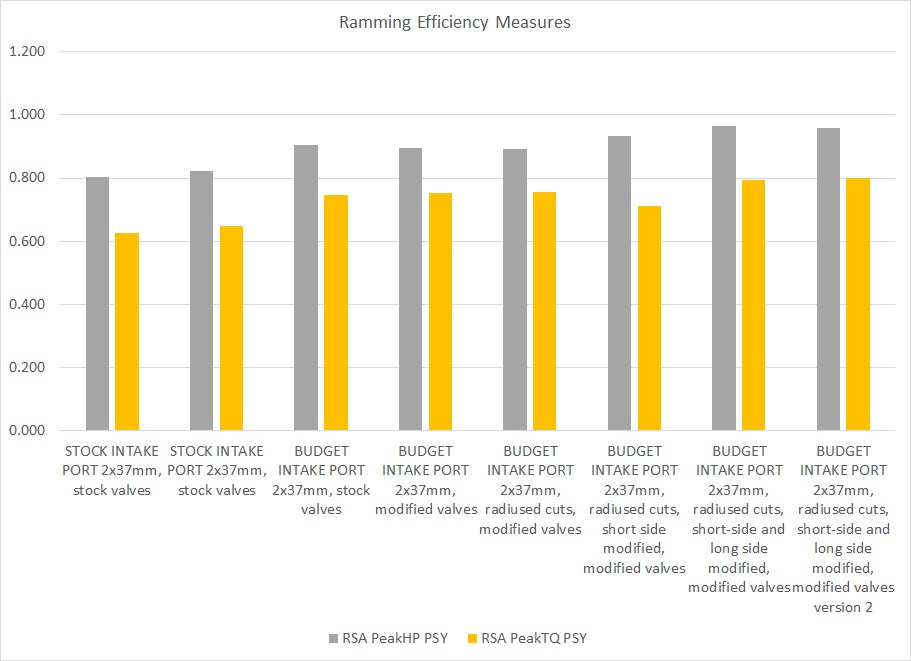
The peak power ramming efficiency numbers are pretty high, and getting higher with modifications.
For reference, the formulas I used to compute these are the RSA regression functions:
Peak HP PSY = CDI^1.52 * AStar^0.48 - 1.5*(CDI - AStar)^2
Peak TQ PSY = CDI^1.56 * AStar^0.44 - 4.3*(CDI - AStar)^2
where
CDI = (port CFM at maximum lift @ 28" / port MCSA in square inches) / 133
AStar = 4.2 / (bore area in square inches / port MCSA in square inches)
The way I read these is that your budget porting experiments are getting the 928 S4 intake port closer to the benchmark level, indicating higher power and torque potential after modifications. Nothing shocking there, in other words.
Tuomo, a few words about my thinking of how to size the exhaust port for the 427CI stroker. It is very simple same CSA for the port as for the ID at the valve seat rings (the throat).
Stock 928S4 head with 33mm exhaust valves: Exhaust port circular 40mm CSA 1257mm2. Throat 28,4mm combined CSA 1267mm2.
Race head with 36mm exhaust valves: Exhaust port oval 50 x 40mm CSA 1657mm2. Throat 32,4mm combined CSA 1648mm2.
Stock 928S4 head with 33mm exhaust valves: Exhaust port circular 40mm CSA 1257mm2. Throat 28,4mm combined CSA 1267mm2.
Race head with 36mm exhaust valves: Exhaust port oval 50 x 40mm CSA 1657mm2. Throat 32,4mm combined CSA 1648mm2.
Last edited by ptuomov; 01-27-2015 at 07:41 PM. Reason: Added RSA measures
01-28-2015, 04:23 AM
#278
Rennlist Member
Join Date: Feb 2011
Location: Mostly in my workshop located in Sweden.
Posts: 2,226
Received 442 Likes
on
244 Posts
As my 427 CI has 108mm bore the correct bore area to valve throat area is 4.23.
Good your theoretical calculations confirm what I see from practical experience point of view.
When it comes to modifying/increasing of the 928S4 exhaust port, I think many people feel themselves limited by the seal ring groove surrounding the port. From pictures I can see some have ground out the floor of the port which is wrong. A colleague of mine did some experiments on a Volvo four-banger once, he raised the exhaust port quite a lot and found the flow numbers were up very much, I do not remember the numbers but it was quite dramatically.
�ke
Last edited by Strosek Ultra; 01-28-2015 at 04:40 AM.
01-28-2015, 09:48 AM
#279
Nordschleife Master
When it comes to modifying/increasing of the 928S4 exhaust port, I think many people feel themselves limited by the seal ring groove surrounding the port. From pictures I can see some have ground out the floor of the port which is wrong. A colleague of mine did some experiments on a Volvo four-banger once, he raised the exhaust port quite a lot and found the flow numbers were up very much, I do not remember the numbers but it was quite dramatically. �ke
I personally think that there's no reason to put a step at the exhaust manifold flange. I'd rather match the header and the port, by hook or by a crook, if both are appropriate size. Different engines have different exhaust port lengths and different operating rpm ranges, wouldn't it be a mighty coincidence if the exhaust port length by chance would be at the spot where the first expansion of the cross-sectional should also be, for all engines and cylinder heads? ;-) If one has to have a step at the header flange because the parts won't fit exactly and the header pipe is a bit too large, I agree it's much better to have a sharp step at the bottom.
My theory (just a theory) is that the first step helps with reversion because it produces a negative reflected wave ("step wave") to the port during the overlap at high rpms. The primary pipe termination reflects the wave ("primary wave") that helps to lower the exhaust pressure at the mid range rpm. The collector termination, at X-pipe or H-pipe for our engines, creates a third wave ("collector wave") that helps with overlap at low rpms. High, medium, and low rpm being interpreted as parts of the intended power band, not in absolute sense.
If the first step is too close to the exhaust valve, the step wave is "wasted" and only helps to reduce exhaust pumping losses. My hunch is that for the first step to be optimally placed at the header flange would require an operating RPM that is not common for car engines.
Furthermore, when the exhaust flow is close to sonic, the reflected pressure wave swims upstream really slowly. Therefore, a small diameter exhaust port and first header pipe step move the operating rpm range down as the period during which the exhaust gas flow is fast and the wave can't swim upstream is longer. Small pipes would require the first step closer to the head, all other things equal, which makes sense.
Ok, back to the salt mines after a snow day off from work. Logout.
01-30-2015, 05:48 AM
#280
Rennlist Member
Join Date: Feb 2011
Location: Mostly in my workshop located in Sweden.
Posts: 2,226
Received 442 Likes
on
244 Posts
Curious whether there are other valves (perhaps from other non-Porsche cars...) with the right diameter and stem length but already shaped with the flatter tulip under the head.
A couple decades ago I found some hi-po aftermarket Chrysler valves for a Rolls-Royce engine that were drop-in replacements at a tiny fraction of the R-R prices. Just needed to use the Chrysler keepers and retainers. There's a pretty amazing supply of valves in the aftermarket.
A couple decades ago I found some hi-po aftermarket Chrysler valves for a Rolls-Royce engine that were drop-in replacements at a tiny fraction of the R-R prices. Just needed to use the Chrysler keepers and retainers. There's a pretty amazing supply of valves in the aftermarket.
01-30-2015, 08:10 AM
#281
Rennlist Member
Join Date: Feb 2011
Location: Mostly in my workshop located in Sweden.
Posts: 2,226
Received 442 Likes
on
244 Posts
I am sitting there before I sent my heads to get machines, and I was thinking about the movement of the valve through its cycle.
Its at max lift once. It's at all other lifts twice. So it seems to me that in the second graph, we need to figure out how to get the blue line higher BELOW 8mm.
Its at max lift once. It's at all other lifts twice. So it seems to me that in the second graph, we need to figure out how to get the blue line higher BELOW 8mm.
Tuomo and I hope the budget porting shown here will inspire more people to do their own porting job. Any avarage handy guy having the right tools, good common sence and good finger feeling can perform a good job. There is no need to spend hugh amount of money handing over the job to the one who says he is the only one able to make the 39mm valves flow more or the one who uses a CNC machine to make the already large intake port even larger.
As you have noticed the major porting work is carried out at the area surrounding the valve seat and at the divided ports. The CSA of the port at the flange/gasket area is already too large and should not be increased unless you are building a very high performance, high revving 427CI stroker having very large intake valves. The rule of thumb sizing the intake port to match
the valves is port CSA being 67% of the valve area. The 1700mm2 CSA of the 928S4 intake port very well match dual 40mm intake valves.
Now I have to continue the work on a full race intake port having 42mm valves.
�ke
01-30-2015, 05:54 PM
#282
Addict
Rennlist Member
Rennlist Member
Join Date: Feb 2004
Location: Monterey Peninsula, CA
Posts: 2,374
Likes: 0
Received 16 Likes
on
12 Posts
Another of my opinions and also from a camshaft engineer on valves.
Once the ports and valves are sized properly, the lift should take into account the area under the curve that correlates to the time of the valve off the seat..
One can trade maximum lift for total open time of the valve by shaping the cam to have a rounder profile that increases the total open time compared to a sharp profile with the same maximum lift. This is caused by the time the valve stays open in the cycle.
In many cases, it is possible to flow more air measured in mass, by using a lower lift cam with a rounder nose that gives the total lift over time a higher value than a sharper nosed camshaft.
As such the analysis on flow should consider total flow over time vs peak flow. (Many look at the peak and not the total as a function of time)
The rule of thumb from that engineer was for most performance applications, 12.7 mm or 0.5 inch was as high as most cam lifts needed to be with a rounder profile cam..
Sent from my iPhone using Rennlist
02-27-2015, 11:33 AM
#283
Rennlist Member
Join Date: Feb 2011
Location: Mostly in my workshop located in Sweden.
Posts: 2,226
Received 442 Likes
on
244 Posts
Now we shall have a look at an experimental full race intake port having 5mm larger dual 42mm intake valves. The CSA of the intake port is enlarged by appr. 10% to 2.878 sqin to match the size of the oversize valves and a high performance 427 CI (7 liter) stroker engine.
In spite this is the best flowing intake port I have ever seen, I am not entirely satisfied with the high lift flow. The valve to valve distance of 2mm is very small creating an area of shrouding between the valves. The next experiment will be a similar port but the valves spread apart by another 3mm which hopefully will reduce shrouding and enhance high lift flow.
For the last iteration of the 42mm valve intake port flow study as I was unable to improve the high lift flow any further, I turned my focus towards the best possible low to mid lift flow without loosing too much at high lift. The flow at 14mm went down slightly from 438,3 CFM (best result) to 435,9 CFM.
All the tricks in the book as being shown earlier have been used. The valve seats were cut using a different #4089 MIRA formtool. In combustion chamber 30dgs x 0,5mm, seat 45dgs x 1,0mm, in port 65dgs x 1,0mm plus 75dgs x 2,0-2,5mm.
The flow test was performed over a bore of 4.250" or 108mm.
Note my flow bench is working at a depression of 10" of water column. The figures have been converted to 28" of depression for easier comparison.
Flow in CFM @ 28" at 2mm, 4mm , 6mm and so on up to 14mm.
88,8 177,7 260,5 327,3 377,5 414,2 438,3 (at 15mm lift 443,8 CFM)
�ke
Last edited by Strosek Ultra; 03-01-2015 at 07:15 AM. Reason: wrong CFM numbers
02-27-2015, 02:43 PM
#285
Nordschleife Master
If you read some posts earlier in the thread, there are recipes by Ake on how to modify the 928 heads in a way that would be an improvement on a much broader set of motors. There's a budget porting recipe for a head that uses the stock 37mm valves. There's another budget porting recipe for a head that uses new 39mm valves and seats.
I think most people here who are thinking about getting some head work done on their 5.0L motor should take a look at the posts in this thread about budget porting with 37mm stock valves. In my personal opinion, beyond those changes to the head, the effort and money are better spent on improving the intake upstream of the head than more radical modifications of the cylinder head itself. This is just my personal opinion, caveat lector.

