
LH 2.2 MAF/CO adjustment LED (85-86 US)


 04-08-2008, 02:42 PM
#33
Inventor
Rennlist Member
Rennlist Member
Thread Starter
Are you using the LED?
04-08-2008, 03:33 PM
#34
Race Car
I have changed the chips back and set the base line for 382 Ohms on the Maf it is still screwed up big time. Stalls when starting after warm up stalls when shifting and cuts out while driving.
No I did not use the LED set-up, Car is running like crap, I put everything back to where is was including the chips. Checked with warm not hot engine the Temp II reads 630 Ohms at both sides and Pin 2 of the LH.
No I did not use the LED set-up, Car is running like crap, I put everything back to where is was including the chips. Checked with warm not hot engine the Temp II reads 630 Ohms at both sides and Pin 2 of the LH.
04-08-2008, 06:43 PM
#36
Race Car
I have no way of measuring it, I can tell you that when I checked the Maf resistance it was at 0 ohms and the A/F was close to ok.
I adjusted the Maf for 383 Ohms and this reading is with the Lm-3 completely removed and only using the Lm-1.
First part of the data above line is with Ox connected, second half is with it disconnected at idle.
Do I still have a problem with the Maf ?
I adjusted the Maf for 383 Ohms and this reading is with the Lm-3 completely removed and only using the Lm-1.
First part of the data above line is with Ox connected, second half is with it disconnected at idle.
Do I still have a problem with the Maf ?
04-08-2008, 08:02 PM
#37
Race Car
Readjusted my Maf from 383 Ohms to 74 Ohms car ran ok but stalled during boost shift. See data logs. My panel and Ecm's are hanging out for now to check all the connections so I could not get into it.
06-18-2008, 04:46 PM
#38
Instructor
Join Date: Dec 2007
Location: Gothenburg, Sweden
Posts: 128
Likes: 0
Received 0 Likes
on
0 Posts
 06-18-2008, 08:09 PM
#39
Inventor
Rennlist Member
Rennlist Member
Thread Starter
Yes.
07-01-2008, 01:19 AM
#40
Inventor
Rennlist Member
Rennlist Member
Thread Starter
This 'feature' was a pain in the **** to utilise, so I've been collecting bits and bobs to make it simpler. Finally today, I was able to set my MAF properly, and much more easily.
I found it won't flash while you are adjusting the CO with the idle jumper, C->B, connected! You have to adjust while the idle is controlled by the LH, then check for flash by going into the idle set mode. The method I came up with follows the pics.
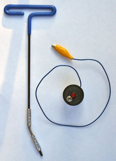
First I needed a special tool to reach the MAF screw while the engine was running. OK, no one stocks the factory tool, a universal jointed 3mm hex driver, 'round here, so I had to make it from a 3mm hex key, and 1/8" SS aircraft cable.
Second, I needed a proper plug-in for the diagnostic LED. Along the way, I realized I needed a switch for the idle, too. The diagnostic plug is a 911/914 relay socket, so I cut open a 91161510901 relay, took the guts out, and installed the switch, a very bright LED + resistor, and a wire with alligator clip to connect to the jump post. You could just as well make this with banana plugs and wires.

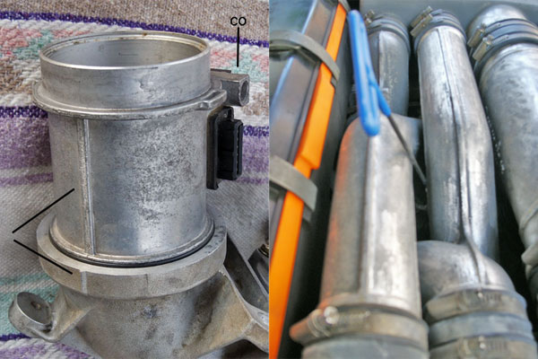
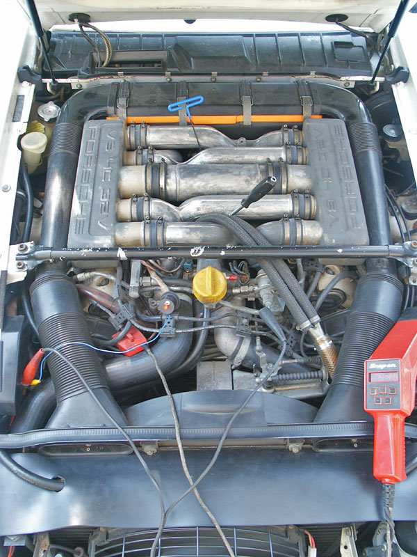
There's a small nub cast into the J-bend, to line up the MAF so that the special tool will fit in! (Ain't that spe-shal.)
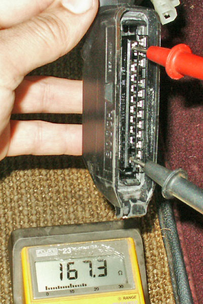
I measured the initial value of the CO adjustment, which by default is 380(?) ohms. Pins 14 (MAF CO) and 25 (ground) on the LH plug. The value shown is what I ended up after adjustment for my engine.
The method
Timing light for RPMs, 7mm socket for the idle screw, CO adjuster, and blinker installed. Engine warmed up, but off, A/C switch off.
The LED will be on until the engine is started. Make sure the idle switch is off or it won't start! Start the engine, and let it settle down. It may take a few minutes for the O2 sensor to heat up again. The LED may be off or on. Turn on the idle switch, and adjust the idle to 680. Turn off the idle switch. The engine will rev up and settle back to 680 �40.
If the LED is off, adjust the MAF screw CW until it is lit. Then, or if the LED is on, adjust the MAF screw CCW until the LED stays on for 3-4 seconds, then off for �-1 second.
While the LED is on, turn on the idle switch. It should stay on for a short time, then start flashing if the adjustment is good. If it goes off and stays off, then the adjustment isn't quite right, yet. Adjust the idle speed again, if necessary. Turn off the idle switch, wait for the idle to settle, and repeat. After a few unsuccessful tries, rev up the engine for a few seconds >1500 rpm to clear out the exhaust.
It's a good idea to shut off the engine occasionally, and check the ohms at the LH plug, to make sure you haven't gone too far one way or the other. The CO adjuster goes from 0-1000 ohms in 14(?) turns. You can't feel the stops.
(Blink'r manual)
I found it won't flash while you are adjusting the CO with the idle jumper, C->B, connected! You have to adjust while the idle is controlled by the LH, then check for flash by going into the idle set mode. The method I came up with follows the pics.
First I needed a special tool to reach the MAF screw while the engine was running. OK, no one stocks the factory tool, a universal jointed 3mm hex driver, 'round here, so I had to make it from a 3mm hex key, and 1/8" SS aircraft cable.
Second, I needed a proper plug-in for the diagnostic LED. Along the way, I realized I needed a switch for the idle, too. The diagnostic plug is a 911/914 relay socket, so I cut open a 91161510901 relay, took the guts out, and installed the switch, a very bright LED + resistor, and a wire with alligator clip to connect to the jump post. You could just as well make this with banana plugs and wires.

There's a small nub cast into the J-bend, to line up the MAF so that the special tool will fit in! (Ain't that spe-shal.)
I measured the initial value of the CO adjustment, which by default is 380(?) ohms. Pins 14 (MAF CO) and 25 (ground) on the LH plug. The value shown is what I ended up after adjustment for my engine.
The method
Timing light for RPMs, 7mm socket for the idle screw, CO adjuster, and blinker installed. Engine warmed up, but off, A/C switch off.
The LED will be on until the engine is started. Make sure the idle switch is off or it won't start! Start the engine, and let it settle down. It may take a few minutes for the O2 sensor to heat up again. The LED may be off or on. Turn on the idle switch, and adjust the idle to 680. Turn off the idle switch. The engine will rev up and settle back to 680 �40.
If the LED is off, adjust the MAF screw CW until it is lit. Then, or if the LED is on, adjust the MAF screw CCW until the LED stays on for 3-4 seconds, then off for �-1 second.
While the LED is on, turn on the idle switch. It should stay on for a short time, then start flashing if the adjustment is good. If it goes off and stays off, then the adjustment isn't quite right, yet. Adjust the idle speed again, if necessary. Turn off the idle switch, wait for the idle to settle, and repeat. After a few unsuccessful tries, rev up the engine for a few seconds >1500 rpm to clear out the exhaust.
It's a good idea to shut off the engine occasionally, and check the ohms at the LH plug, to make sure you haven't gone too far one way or the other. The CO adjuster goes from 0-1000 ohms in 14(?) turns. You can't feel the stops.
(Blink'r manual)
Last edited by PorKen; 04-03-2010 at 03:04 PM. Reason: link to manual
04-02-2010, 10:46 PM
#41
Team Owner
thanks for posting this Ken
11-21-2012, 12:44 PM
#42
Sharkaholic
Lifetime Rennlist
Member
Lifetime Rennlist
Member
S300s chipset
� Set CO at 680 rpm then:
- 5-speeds, turn screw (2) full turns CCW
- Auto, one turn CCW
� Blinking may take a second longer to
start when idle switch is set to right. Have
patience.
� Set CO at 680 rpm then:
- 5-speeds, turn screw (2) full turns CCW
- Auto, one turn CCW
� Blinking may take a second longer to
start when idle switch is set to right. Have
patience.
11-21-2012, 02:33 PM
#43
Inventor
Rennlist Member
Rennlist Member
Thread Starter
That's a bit unclear.
Turn the -idle speed screw- out 1 or two turns.
Still is a good idea with V4.0
Turn the -idle speed screw- out 1 or two turns.
Still is a good idea with V4.0
11-21-2012, 02:51 PM
#44
Sharkaholic
Lifetime Rennlist
Member
Lifetime Rennlist
Member
Okay got it, was thinking the Maf adjustment screw not the idle screw. Thanks for clarifying.
I'm guessing on the idle as my timing light doesn't have an RPM readout so I'm using the tach.
I'm guessing on the idle as my timing light doesn't have an RPM readout so I'm using the tach.
04-01-2013, 01:30 AM
#45
Burning Brakes

Join Date: Mar 2012
Posts: 868
Likes: 0
Received 0 Likes
on
0 Posts
Thanks for details,
Scott.