
H5 to H4 conversion with electric adjusters
 06-04-2005, 02:45 AM
#1
Electron Wrangler
Lifetime Rennlist
Member
Lifetime Rennlist
Member
Thread Starter
Well I finally started this long planned project. My H5's are out and will be listed on ebay tomorrow if anyone is looking. I was really impressed with how clean they were under the pod covers. The adjusters were a little stiff until I lubed & greased them a bit but otherwise excellent. Well they are out and the H5 connectors are history and H4's soldered in and tidied up. If that were all I was going to do it was incredibly easy.... < 1 hour job
But I had decided I wanted the full "original European design experience" (DOT Illegal and all !! - although I suspect It would now be legal today anyway). I've been hunting down a set of electric headlight adjusters and Pot/**** for a while and got one about a month ago - used equipment from a breakers yard in the UK. I already knew that the wiring loom for the switch was in place under the handbrake cover so I expected that the wiring loom in the fenders was just hanging loose similarly just waitng for the motors to be pluged in. Well great theory - but alas not - I can't find any sign of the loom and turns out there is a plug in loom for these that pulgs behind the central electric - so maybe US cars never had this loom option installed? I haven't got that far yet - but have added new wiring to both adjusters motors in the pods and tomorrow will attempt to route it all including through the firewall to central electric. Given no loom there are also no connectors so I had to fabricate these from scratch also - a real pain in the ***!
Now for the other gotcha. It wasn't obvious to me how the motors attached until I disassembled the H5's. The ball joint locator of the H5's is a mini version of the motors and the attachment is the same - 3 tab locator pinch ring with a rubber grommet behind. works well on the round fixed locator of the H5's. On the H4's the whole headlamp frame pivots in the middle vs getting bolted flat and the motor at the frame bottom tilts the whole lens.
Great in theory by the motors are big and with the fork in place alignining the motors is tricky enough - when it comes to twisting the locator ring the headlight body plate gets in the way and you can't pivot it enough to get the tabs in...? WTF!! Such an elegant mounting method but seems I need to remove the pivot fork to be able to insert this...? Kind of defeats the purpose of a quick release mounting??
Is there some other way?
Seems I will have to remove both front wheels & liners, diassemble the fork mechanisms - install the motors (wil take 2 seconds!!) and then rebuilt the forks etc...
Is it really this hard ?
Anyway - whetever it takes I will get them in in the next week - right now the H5 ball locator things are back in and the H4's are working and the adjuster motors are dangling in free space under the headlights...
Anyone BTDT ? ... probably not?
Alan
Last edited by Alan; 06-04-2005 at 03:02 AM.

 06-04-2005, 05:41 AM
#3
Rennlist Member
Alan,
I think you can get by just popping the pod covers and wheel liners. You can probably leave the wheels on, just turn the wheel to get it out of the way. Turn the wheels with the engine running so you don't stress steering parts.
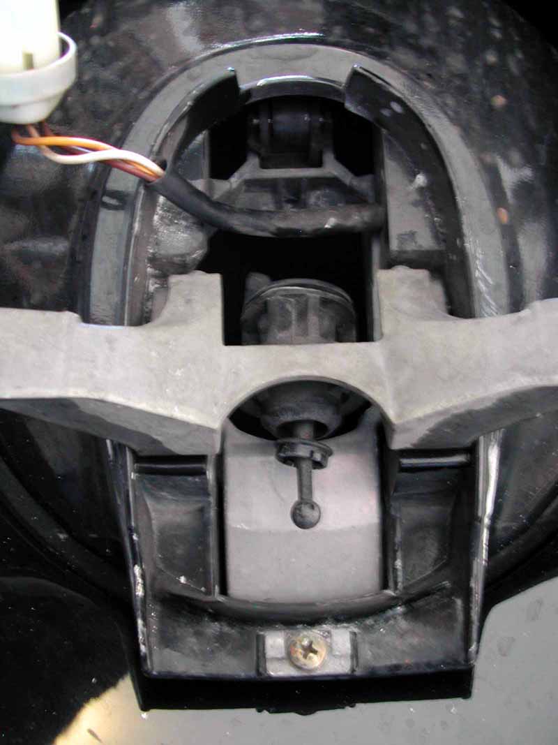
Anyway, in the first pic you can see down the axis of the factory adjuster motor(hydraulic version). The wheel above that is a spring-detent type of mechanism which is what holds the yoke to the bar. In the second pic is the other side... at the top of the black piece you can see the spring and rocker arm that are part of that spring-detent, and you can see the ramp in the white plastic that the roller engages with.
Now, with the lights in the down position, reach into the fender and lift upward on the pod base... the large white plastic section in the second pic. Once you get the roller over the ramp, the pod will pop free and will pivot freely on the headlight pivot bar as far as the full "up" position. At this point you should have free and easy access to the motor, so long as you hold the light in the "up" position. I think what's been giving you fits is the black piece in that second pic that is solidly attached to the headlight pivot bar, and it will prevent you from getting at the motor from the bottom if the headlights are raised via the headlight motor at the start of the project.
I'm not sure why they did it this way... it's not like Porsche to engineer such an elaborate mechanism just so you can access a relatively inconsequential device. I think that was just an afterthought.
My running theories on this are:
- They did it for pedestrian safety -- so you won't pinch someone's *** with the light if you turn it off when they are sitting on the fender(though if someone sits on my fender you can bet I'll KICK their *** )
)
- They did it because in snowy/icy conditions the light pod can get frozen in place or blocked up with icy snow, which would jam the mechanism when attempting to lower the pod
Anyway, the upshot is, you should be able to get in there without disassembling too much. Though I think your fender liners are a much bigger PITA than mine to take out.
HTH
I think you can get by just popping the pod covers and wheel liners. You can probably leave the wheels on, just turn the wheel to get it out of the way. Turn the wheels with the engine running so you don't stress steering parts.
Anyway, in the first pic you can see down the axis of the factory adjuster motor(hydraulic version). The wheel above that is a spring-detent type of mechanism which is what holds the yoke to the bar. In the second pic is the other side... at the top of the black piece you can see the spring and rocker arm that are part of that spring-detent, and you can see the ramp in the white plastic that the roller engages with.
Now, with the lights in the down position, reach into the fender and lift upward on the pod base... the large white plastic section in the second pic. Once you get the roller over the ramp, the pod will pop free and will pivot freely on the headlight pivot bar as far as the full "up" position. At this point you should have free and easy access to the motor, so long as you hold the light in the "up" position. I think what's been giving you fits is the black piece in that second pic that is solidly attached to the headlight pivot bar, and it will prevent you from getting at the motor from the bottom if the headlights are raised via the headlight motor at the start of the project.
I'm not sure why they did it this way... it's not like Porsche to engineer such an elaborate mechanism just so you can access a relatively inconsequential device. I think that was just an afterthought.
My running theories on this are:
- They did it for pedestrian safety -- so you won't pinch someone's *** with the light if you turn it off when they are sitting on the fender(though if someone sits on my fender you can bet I'll KICK their ***
)- They did it because in snowy/icy conditions the light pod can get frozen in place or blocked up with icy snow, which would jam the mechanism when attempting to lower the pod
Anyway, the upshot is, you should be able to get in there without disassembling too much. Though I think your fender liners are a much bigger PITA than mine to take out.
HTH
06-04-2005, 02:02 PM
#4
Electron Wrangler
Lifetime Rennlist
Member
Lifetime Rennlist
Member
Thread Starter
Dave,
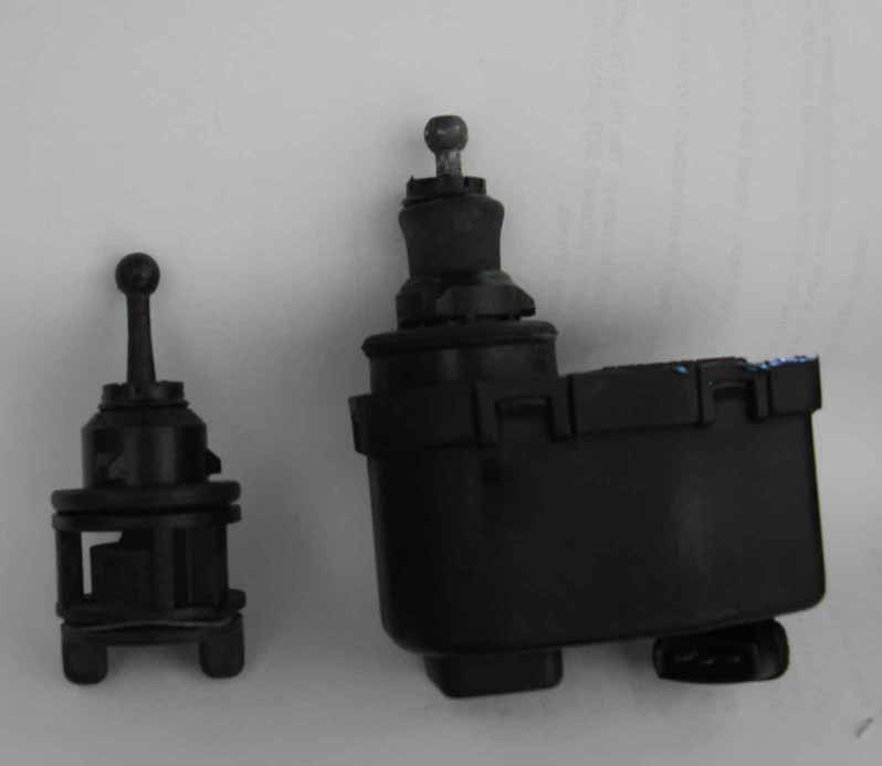
Thanks for the Photos. I don't think the issue is the black part - with the light down but the HL pod pulled up you can get clearance from this - this how I got the dummy adjusters (US fixed versions) out - seems from your photo that the hydraulic versions are a similar size (probably the US versions are just fixed version of the original hydraulic set up). The hang-up I have is with the body color base panel under the pod, the underside of this gets in the way of the electric adjuster rotation inside the fork/yoke
However the biggest reason for this is that the electric adjusters are JUST HUGE in comparison and are not cylindrical - the main part of the body is offset from the shaft. This is what makes rotating it impossible. I guess the electric versions were made because of all the issues with hydraulic versions and just adopted the mounting method even although its now basically non-functional as originally intended for removal in-situ.
Location of the dummy adjusters - easy to remove/replace
See the slight difference:
The easy part - my new H4's looking good!
So wheel liners here I come... Dave do you have a picture of the bottom side of the body color base panel showing where/how the yoke attaches to it ?
Thanks,
Alan
06-04-2005, 02:17 PM
#5
Rennlist Member
AFAIK it's just the two allen screws coming up from the bottom side. One is fully visible just to the left of the black piece in my second photo; the one on the other side is partially obscured but still visible on the opposite side.
06-04-2005, 02:18 PM
#6
Under the Lift
Lifetime Rennlist
Member
Lifetime Rennlist
Member
Getting the wheel well liners off with the wheels in place requires too much contorting to get to all the screws and impedes access to the bottom of the headlamp mechanism. Just jack the car up and remove the wheels.
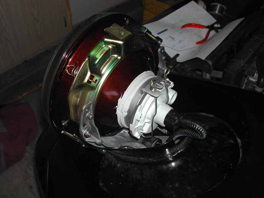
Yes, the balljoints are different, including the length. If you leave the H5 yoke and balljoint in place, as I did, the H4 headlamp sits out 1/4 inch further when adjusted to the proper angle and this causes some problem with getting the pod covers to catch on the posts that prevent them from flapping.
So, I gather you have the Euro motors but not the aluminum U yokes? Is that the problem? Mine came with the motors on the yokes, so I would have just removeed the wheel liners, removed the yoke. I'm not sure if the US yokes can accomodate the motors. Either way they would have to come off.
06-04-2005, 02:30 PM
#7
Electron Wrangler
Lifetime Rennlist
Member
Lifetime Rennlist
Member
Thread Starter
Dave - thanks I see it and thats all I could feel blind from top side.
Bill - thanks - I don't think the yokes are different - at least I think the motors will fit fine once the yokes are out. Yep I assumed I'd need to remove the wheels & liners, after 30 minutes of fiddling about - you realize its not going to happen.
What did you do for the wiring - did you find a wiring harness in there already? how about under handbrake cover.... If not what did you do to solve that? - any tips on routing - my wiring is just into the engine bay ahead of the radiator at this point.
Alan
Trending Topics
06-04-2005, 03:29 PM
#8
Under the Lift
Lifetime Rennlist
Member
Lifetime Rennlist
Member
Alan:
Sorry, I have not done the motor conversion, just popped the H4 in with the H5 yoke, so it pivots but is using the non-motiorized H5 balljoint. So, I don't know about the harness. You are ahead of me on that. If you get the motors mounted and wired in somehow, please post. I can't recall hearing of anyone else doing that although a lot of us have installed the H4 lamp units without the motors.
Sorry, I have not done the motor conversion, just popped the H4 in with the H5 yoke, so it pivots but is using the non-motiorized H5 balljoint. So, I don't know about the harness. You are ahead of me on that. If you get the motors mounted and wired in somehow, please post. I can't recall hearing of anyone else doing that although a lot of us have installed the H4 lamp units without the motors.
Last edited by Bill Ball; 06-05-2005 at 01:33 AM.
06-04-2005, 04:45 PM
#9
Electron Wrangler
Lifetime Rennlist
Member
Lifetime Rennlist
Member
Thread Starter
FYI - I did list my "old" H5's on Ebay. They are as nice a used set as you could get. Great for a 7" upgrade - if anyone here wants more details, installation info or photo's just let me know (PM me).
Hey - did you see that new H5's are quite a bit more expensive than new H4's (huh ?)
Alan
Hey - did you see that new H5's are quite a bit more expensive than new H4's (huh ?)
Alan
Last edited by Alan; 06-06-2005 at 08:41 PM.
06-05-2005, 12:14 AM
#10
Electron Wrangler
Lifetime Rennlist
Member
Lifetime Rennlist
Member
Thread Starter
All,
I did find the connector for the electric adjusters above/behind the central electric. See the photo below. The wiring on the right (top 3 anyway) goes to the handbrake cover where the pot connector is on my car - on the left side of this connector - nothing is there - so confirmation the loom to the front is omitted in US cars (but at least I have both halves of the connector!!).
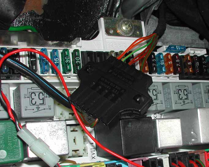
The 2 pairs of Brown/Green wires at the bottom on the left & right are nothing to do with the adjusters and don't show up in the FWM. Not sure what they are... but they are presumably why I have both halves... anyone know what these are for?
Alan
I did find the connector for the electric adjusters above/behind the central electric. See the photo below. The wiring on the right (top 3 anyway) goes to the handbrake cover where the pot connector is on my car - on the left side of this connector - nothing is there - so confirmation the loom to the front is omitted in US cars (but at least I have both halves of the connector!!).
The 2 pairs of Brown/Green wires at the bottom on the left & right are nothing to do with the adjusters and don't show up in the FWM. Not sure what they are... but they are presumably why I have both halves... anyone know what these are for?
Alan
06-05-2005, 12:46 AM
#11
Electron Wrangler
Lifetime Rennlist
Member
Lifetime Rennlist
Member
Thread Starter
Bill,
Read your site details on H4's - nice write up & photos - helpful to me.
A few notes for you:
Got my H4's new from 928 Specialists - they come with everything needed already mounted as you say - except H4 connectors of course and the nuts for the pivot bolts - I got stainless steel (M4's I think) w/ nylon lock bushings and some stainless wave washers.
According to Dave Roberts there is no rubber seal for the connector. I too was expecting one - of course the back of the H4 bulb connector is a great pressure seal to the bulb & lens so the only protection provided by a typical rubber boot would be for connector corrosion - Probably less of an issue on the big H4 connectors (than on H5's) but sealing is the one area the H5 connectors have an edge.
The euro electric adjuster has a screw in ball joint (cross head slot in the end) for initial adjustment - so you could use that for more adjustment (and for general aim) rather than the US fixed version... but agreed installation is a pain.
By using the H4's in their frame you do loose the US H5 aiming adjustment mounted at the back of the pod and accessible without cover removal. Not a big deal to take the covers off and this is not a great mechanism - you may well need to take the covers off to lube it to get it to work anyway - but possibly one less convenience. I believe its possible to transplant the H4's into the US H5 backing frame to keep this feature... but much more work - prob not worth it but some have done it.
I found that a 45 degree angled crank screwdriver was highly desireable for pod cover removal due to body panel interference and I agree - open the hood!
Alan
06-05-2005, 01:38 AM
#12
Under the Lift
Lifetime Rennlist
Member
Lifetime Rennlist
Member
Alan:
I thought the real H4 plugs would have some kind of weather boot. Just seems in heavy rain, an open connector like the aftermarket H4 plug I bought is asking for trouble.
Yes, I guess I forgot to mention in my write up that you lose the external adjuster that is part of the H5 frame. I traded my H5s for the H4s so didn't have a chance to look at a transpalnt. No biggie. Once the H4s were set, I haven't needed to adjust them.
It would be cool to have the electric adjuster functional. I don't suppose the wiring would be hard to create. Does the shop manual wiring diagram help?
Last edited by Bill Ball; 03-26-2006 at 01:54 PM.
06-05-2005, 02:22 AM
#13
Electron Wrangler
Lifetime Rennlist
Member
Lifetime Rennlist
Member
Thread Starter
Bill,
I will write it up when I am done. Frankly the whole thing is more of a pain than I expected. I will prevail though!! In some ways finding the parts is the hardest - and though you have the motors they will not work without the switch/potentiometer (start looking). Based on me having everything it would still be very hard to reverse engineer parts of this system to fab up yourself.
The way it works as far as I can deduce is that the Potentiometer **** (its actually 1 pot + 3 fixed resistors) sets a voltage value and the electronically controlled motors drive a feedback potentiometer as well as the adjuster shaft (rather like the memory mirrors & seat) and will accurately replicate a fixed position wrt the **** position and once set will maintain absolute position accuracy and therefore also relative position between L/R.
Now I'm just beginning to think this might be over engineered a bit...!
Whats wrong with a simple up & down control (a switch) that drives 2 slowly moving motors L/R - set-up so either one getting to the end of its track stops them both so they can stay relatively positioned - the absolute positioning seems rather uneccesary to me...
Getting something else through the firewall will also be challenging (BTDT)as well as routing through the engine compartment.
Another bigger challenge I have is that though I have the wiring diagrams and the potentiometer end wired in (it also has terminal ID's that match the FWM) I do not have the connectors for the motors and they have 3 pins and of course no labelling. I've made a connector but I'm pondering 1-2-3 or 3-2-1.
I will just have to take a shot at it - I've measured the resistance across all three pins but nothing conclusive - no values in the FWM - so tomorrow is the big day to try it out.
So a lightly fused line and my best logical guess... don't know what else to try.... (so it will probably turn out to be 3-1-2 or 1-3-2...)
I'm pondering taking off a motor cover - a bit leery of breaking it (old) - & not sure it will tell me much anyway... haven't decided yet - too much wine tonight to consider it more - sober thoughts tomorrow!
Anyway I hope eventually this will save anyone else the hassle of figuring it out...
BTW I don't think that even in heavy rain the H4 connector is very likely to get wet unless you are going very very fast - the main water channel will be around the lens front edge & down - maybe back to the bulb seal flange and down - since there is minimal airflow inside the covers (of course that may be a different @150MPH).
Alan
Last edited by Alan; 06-05-2005 at 02:45 AM.
06-05-2005, 09:14 PM
#14
Electron Wrangler
Lifetime Rennlist
Member
Lifetime Rennlist
Member
Thread Starter
Well,
After a good while, quite a bit of swearing & backache the electric adjusters are in and they work!
I did have to remove both front wheels, the two well liners per wheel, remove the H4's again! unbolt the yokes from underneath, attach the motors to the yokes out of the car then reinstall (two hand manouver one on top the other underneath through the wheel well (ahh my back!) rejigger the wiring several times (there is very little clearance here) and bolt it all back up.
The connector wiring truned out to be 321 vs my guess of 123 (but no damage)
I now have the connector ID's for the motor plugs a pretty effective way to make the connectors you need out of female bullet connectors & shrink wrap - it works much better than it sounds.
I can tell you it was a sweet moment when both headlight beams tracked up & down the wall together. The adjustment is medium speed and with the H4's its really easy to see the sharp cutoff & this really helps. Positioning is precise turn the **** & they start to move & keep going till they equalize to the set point
Now for what is left - I was unable to get another cable through the firewall and so this was all done with a temporary wire snaking around from the hood to the door & central electric. I need to get the car up on a lift so I can feed it through from the engine bay side - don't want to risk damaging any other wiring so probably next weekend for this if I can persuade my local wrench to let me use his spare lift . This time I'll run a loom with a few extras just in case of future expansion needs?
I have not fully aligned the headlights yet (for base position) They were aligned before the adjusters went in but they threw it right off due to different ball joint lengths. The electric adjustment range is quite substantial and should eliminate any need to ever redo the base alignment. Pod covers went back on with no issues at all - perfect alignment the first time.
BTW in the front drivers wheel well below the headlight I found the feed tube for the alternator cooling just laying there, temperature sensor in place but not getting any air - not obvious where this attaches for intake? anyone? - The alternator end is a bit frayed but connected up.
Few thoughts I had:
Why didn't Porsche bolt the yokes on from the top down instead of bottom up?
Why put "almost" captive nuts on the part that hinges 90 degrees ?
I wish I had a helper - but I've learned it doesn't work to get my wife to "help"
I will post a detailed write up with pictures when I'm fully done!!
But it is a possible retro-fit for any of you other masochists out there!
Alan
06-06-2005, 12:19 AM
#15
Under the Lift
Lifetime Rennlist
Member
Lifetime Rennlist
Member
Good work Alan!
Regarding the air tube for the alternator -- there is a bracket that screws on the the front wheel well cover about 1/2 the way up. You should be able to get the bracket. The bracket consists of two semi circles joined like a "W". It holds the tube near the end in an upside down U, so the tube comes up through one side of the W and loops to go down through the other half. It is a pain to get the tube in the bracket, hold it against the wheel well cover and try to screw it on as there is barely enough slack in the tube to do this. Might be best to detach the tube from the alternator to allow more slack. The bracket makes taking the wheel well cover off more of a pain too. Not surpised it is missing. It probably is not too critical, but there must be some reason it hold the tube in an inverted U. You could probably use tie wraps through the screw holes to hold the tube up there.
Regarding the air tube for the alternator -- there is a bracket that screws on the the front wheel well cover about 1/2 the way up. You should be able to get the bracket. The bracket consists of two semi circles joined like a "W". It holds the tube near the end in an upside down U, so the tube comes up through one side of the W and loops to go down through the other half. It is a pain to get the tube in the bracket, hold it against the wheel well cover and try to screw it on as there is barely enough slack in the tube to do this. Might be best to detach the tube from the alternator to allow more slack. The bracket makes taking the wheel well cover off more of a pain too. Not surpised it is missing. It probably is not too critical, but there must be some reason it hold the tube in an inverted U. You could probably use tie wraps through the screw holes to hold the tube up there.
Last edited by Bill Ball; 06-06-2005 at 02:24 AM.