When you click on links to various merchants on this site and make a purchase, this can result in this site earning a commission. Affiliate programs and affiliations include, but are not limited to, the eBay Partner Network.
Trying to drive the early 944 tachometer with an aftermarket ECU. The DME and entire DME harness is gone, along with the DME relay, so all signals and power/ground connections that were transmitted via that loom are no more.
I connected my "tach out" from my ECU to the yellow and black wire under the steering column (one of the two wires in that connection) which normally goes to the DME pin responsible for the tach signal and nothing happened. The black wire next to it was left floating.
Attempt 2 was hooking up my tach wire to the green wire, which is normally connected to the ground terminal of the coil. My thinking was that older cars got a tach signal from the coil, so maybe it was worth a shot. Again, nothing.
(for anyone curious, the "green wire" goes the connector behind the brake booster. the DME pulses a ground to the coil and this smaller wire tees into it to get a signal).
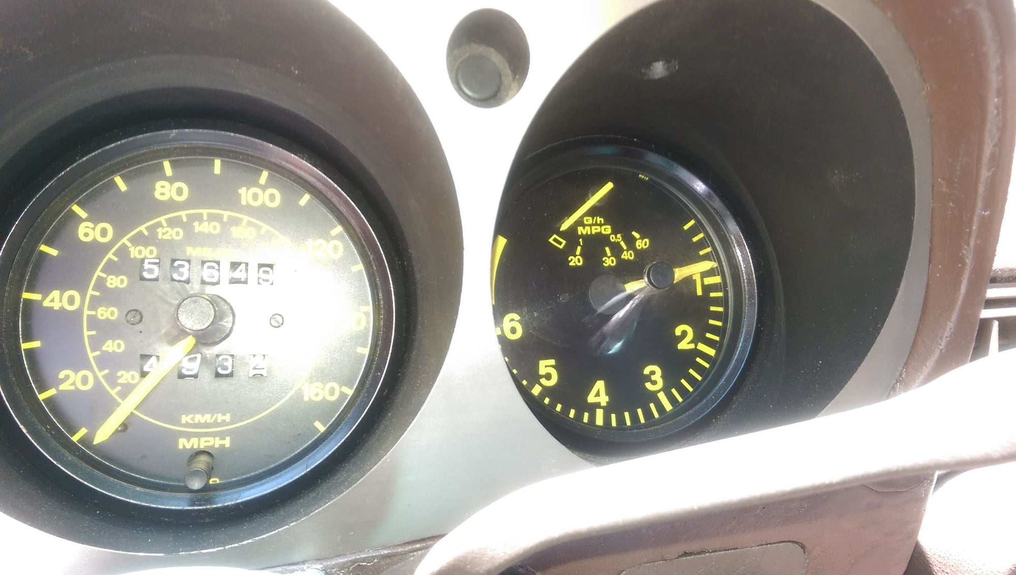
So what's the next move? Is it possible that it was powered by one of the components I removed? I tried using the factory wiring diagram as a reference but I'm not getting anywhere. Everything else is 100% functional (except economy gauge, which always reads maximum). The Megasquirt tach signal itself should work with this tach.
That tachometer is the most f***ed part of the electrical diagram I have looked at, and that is saying something. It looks like the black wire of the tach is connecting to the hot side of the injectors, so we know that should get 12V when the car is running. That power came from the DME, so you might have cut off that power source when you went to your new injector setup. Green/red connects to the radio relay with absolutely no indication of what it does, so who knows about that one. I can't even figure out how the tach gets grounded. It does look like the yellow/black wire must be the tach output since it goes straight from the DME to tach with no other connections. Good luck.
Can you post a pix of the dash schematic for your car?
Edit...look at edredas post about half way down. Figure c18 shows black + and the yellow/black to be the mpg gauge/gage. So green should get you going if the black wire is hot...if that's your version. wiring fun here
Last edited by thomasmryan; 08-06-2015 at 04:44 AM.
Good info guys, thanks! I'll power up the black wire and give it another go. I also thought the black/yellow was for the economy gauge... but all the DME pin assignment charts list it as "tachometer." Weird. I've also heard it's a fuel injector duty cycle signal for the economy gauge.
After more looking, I am pretty sure you need green-signal, black-power, and brown-ground. Yellow/black is the injector width signal that indicates fuel consumption, and while that square wave could theoretically be used for RPM detection, I don't believe it is.
Thanks for lead on the black wire - that was the ticket! The winning combination was +12v to the black wire under the dash and the tach signal going to the green wire (I grabbed it behind the brake booster).
 08-05-2015, 04:06 PM