When you click on links to various merchants on this site and make a purchase, this can result in this site earning a commission. Affiliate programs and affiliations include, but are not limited to, the eBay Partner Network.
I'm mapping out how I want to build my harness. I should be ordering wire and parts for it this week. What gauge wire did you go with? Are you using shielded wire for anything?
I'm mapping out how I want to build my harness. I should be ordering wire and parts for it this week. What gauge wire did you go with? Are you using shielded wire for anything?
I ordered 12 gauge high-temp" wire from McMaster Carr and spent a few hours today working with it, figuring that overkill on the wire would ensure longevity and resist thermal fatigue. Turns out it's really hard to work with relative to the 16 gauge (eyeballing it) wire on the MicroSquirt harness, and requires a lot of solder and heatshrink to make a good and solid connection.
I would recommend going with 14-16 gauge, heat resistant. Maybe even less for sensors, which don't see much current at all. But just use your best judgement, the parts seeing the most current are related to fuel injection and ignition. I would plan on 20 gauge at the thinnest.
I'm not shielding any wiring....should I be? The only shielded wire in the stock harness that I know of is the reference sensor harness. I'm using a hall sensor (where the stock sensors are low voltage VR) so I'm thinking shielding will be unnecessary since the signal processing is done on-board. Someone step in and correct me if I'm wrong. Shielding wouldn't hurt, most people apparently just ground the shielding to the sensor side.
Fun to look at and helpful for choosing the correct size. You can measure and determine the size you have. 12 guage is pretty stout stuff from a current point of view.
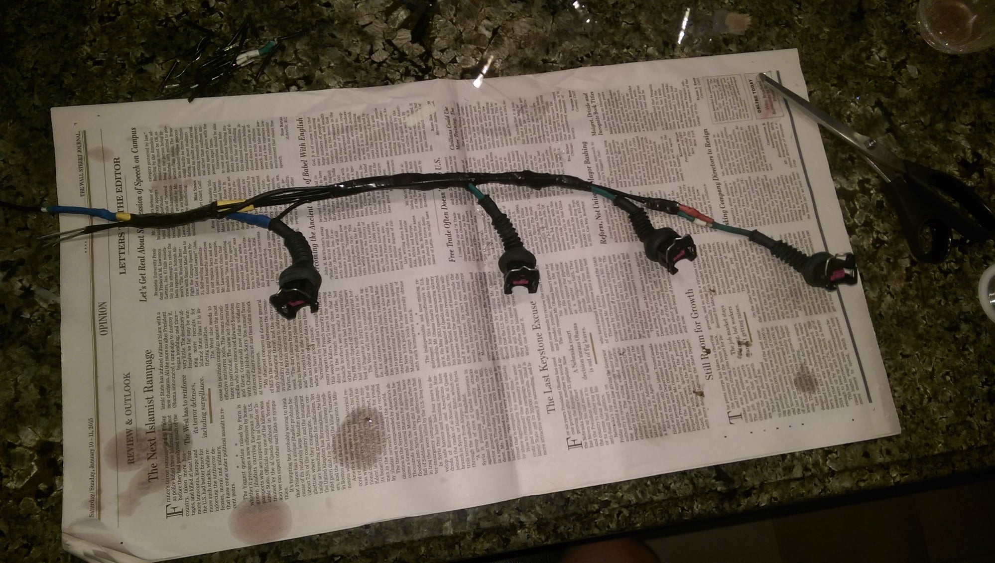
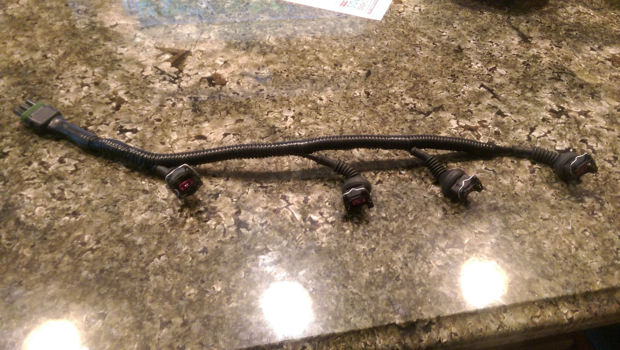
Yeah, in hindsight I should have used thinner wire. I ended up using about 8 feet on the injector harness:
Still have a little wire wrapping to do, but it's functionally ready. I used connectors intended for a mid 90s Mercedes C-class, they are a lot nicer than the stock ones and have a simple release mechanism instead of that silly clip. I soldered everything and used a lot of heatshrink just to be sure, this has to be a bulletproof area because of all the vibration.
I wired all 4 injectors together on the +12v side, which is the big ugly yellow and blue junction. This will be powered via the same relay (main relay) that powers MS, activated by the ignition switch. MS controls the ground side of the injectors, the same way our DMEs do. Since this is a batch fire setup, 1 and 4 are joined and 2 and 3 are joined (because firing order is 1-3-4-2). So you end up with 3 leads - one power which supplies all 4 injectors, and two ground branches, one for each injector channel.
The resistance between the power line and each ground branch is ~6 Ohms, which checks out, because they are 12 Ohm injectors wired in parallel. This is good because MS can drive each pair as though it were a single low-z injector.
For example, although I like the black boots personally cause you can pull them back easily and inspect.
Re: VAG coils... multiple people have referenced them being unreliable, are you thinking of Audi 1.8 units? I really like the look of them, let me know how it goes. I would love to use them over the LS coils because of mounting. How are they controlled? My understanding is they are "dumb" coils that get a 5v signal. The other two wires are 12v and a ground. MicroSquirt is more limited I guess, I'm betting your MSII is better prepared for that setup.
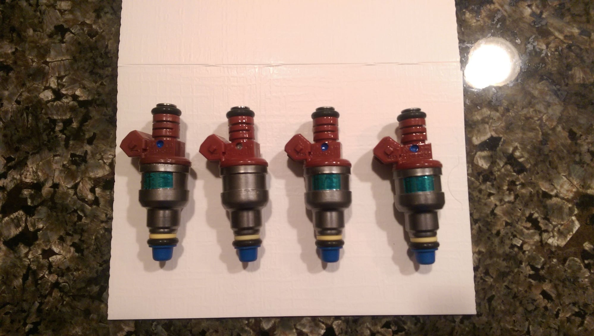
Got these in today, 33# injectors (rated at 3 bar, will be closer to 30# at 2.5 bar). The main reason is that these are high-z (12 ohm), so MS can batch-fire them without anything being weird or needing resistor packs. They are from a Saab 2.3 turbo and have been rebuilt and flow matched.
Also have some high-temp wire from Mcmaster-Carr now, will be building the injector harness tomorrow and mapping some basic power and ground lines.
You have been a power house on this big project. I like your choice of injectors also. Great work!
...how did you know the injectors would physically fit your application?
You have been a power house on this big project. I like your choice of injectors also. Great work!
...how did you know the injectors would physically fit your application?
Thanks! Someone had told me that most Bosch injectors had the same dimensions so I shopped around to find a set that were high-z for a reasonable price and had sufficient flow. These are 0 280 150 431, for $98 shipped with a 5 year warranty. Figured if they didn't work out I could return them but they seem like they will go in no problem. Comparison to stock:
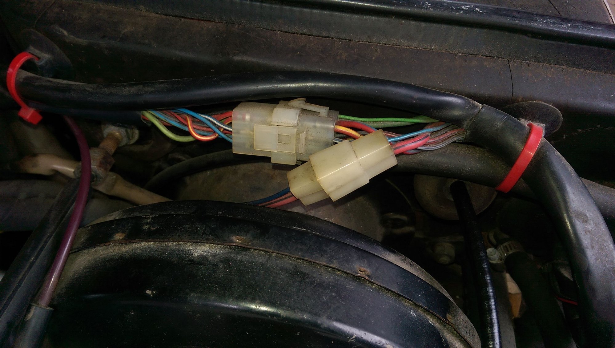
Does anyone have information on some of the factory harness connection? In particular, the interface between the DME loom and the relay/fuse panels.
I opened it up and measured some of the pins relative to ground. I didn't get anything useful... the ones with finite readings were like 140 ohms, 18 ohms, 44 ohms, etc.
Just wondering if anyone knows the pinout for that connector. I'm assuming the DME relay wiring is there, but there are 9 pins... what are the rest?
The factory wiring diagrams should have the information you need.
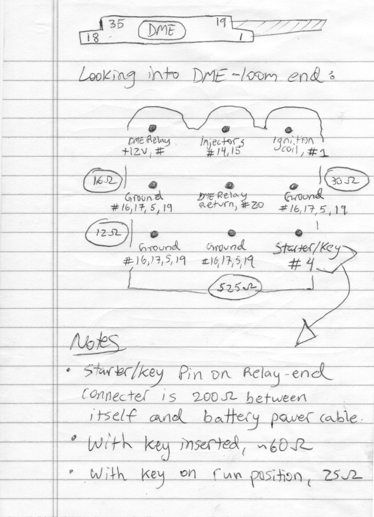
After studying that and doing some multimeter probing, this is what I came up with. This is an early car, those with late cars may not even have this connector.
I'm confused by the "starter/key" pin. I thought maybe it was the ignition switch but it wasn't on or off. See the text in the bottom of the above pic to see what I mean.
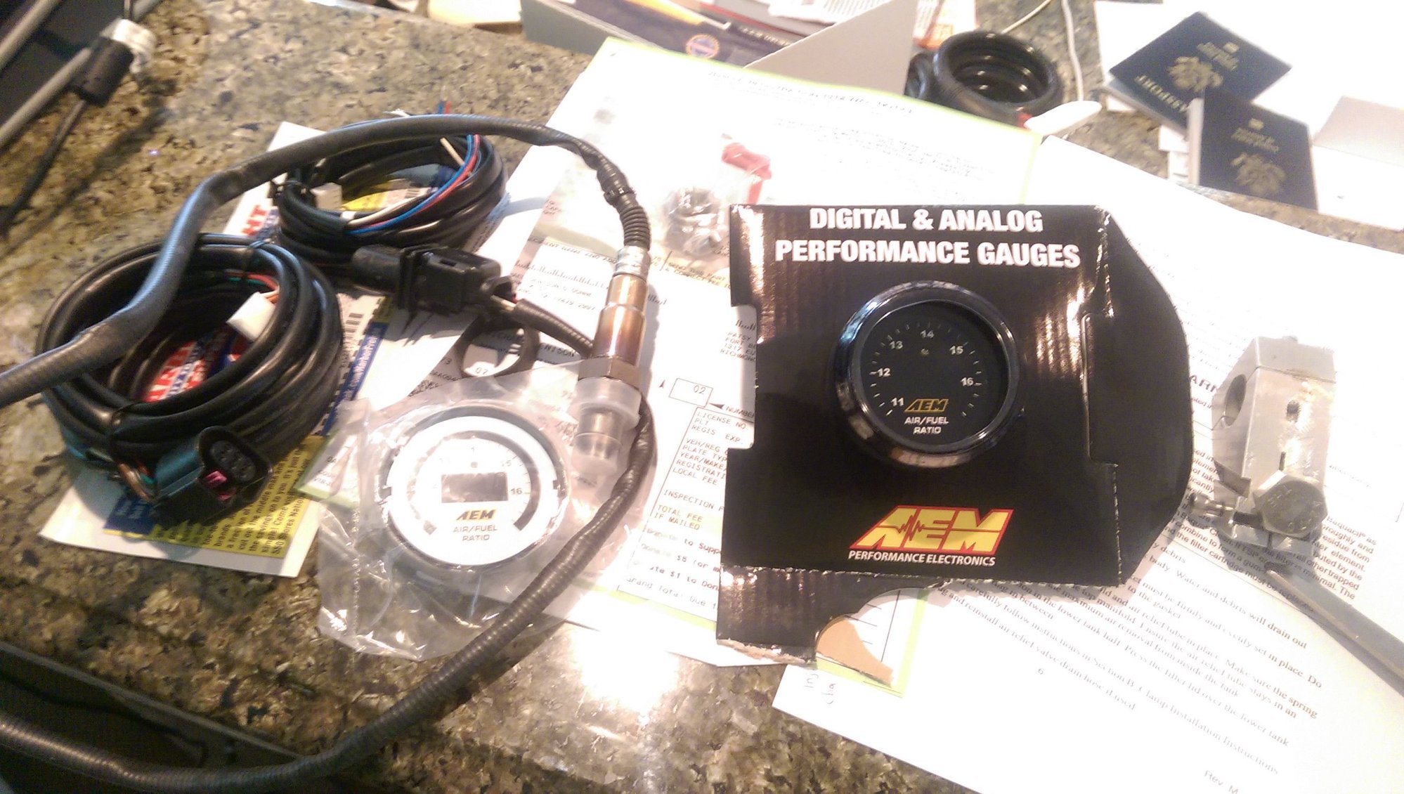
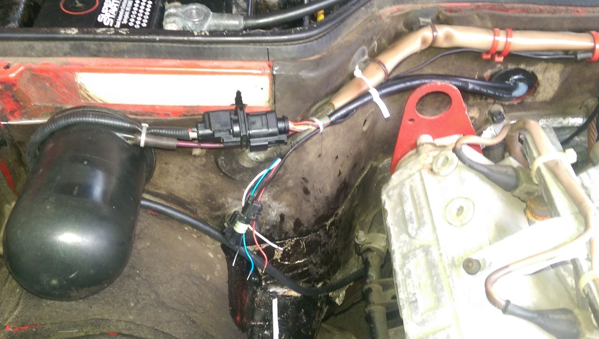
Got a good day to work and installed the wideband O2 (AEM UEGO) and squared away the hall effect sensor mount.
Pardon the POR-15 all over the lower part of the engine bay.
Just need to install the gauge now...
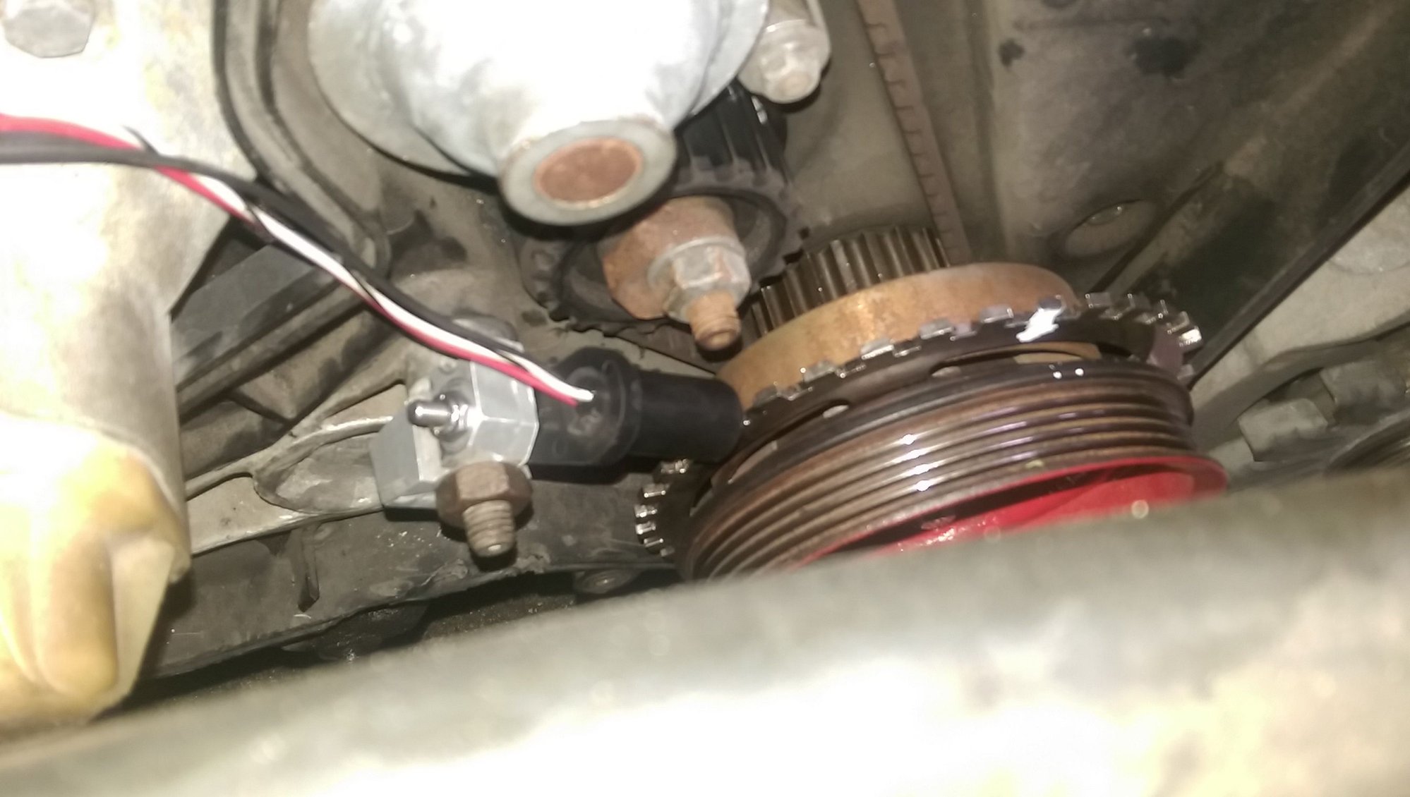
Voith's bracket got here, but unfortunately my tensioner strut for the alternator was in the wrong place relative to the trigger wheel. I ultimately decided to modify it and install it at the 10 o'clock position. My balance shafts are fully deleted, so that opened a few possibilities. Hopefully I can get the timing cover over it, otherwise I guess I'm going to have to cut a hole...
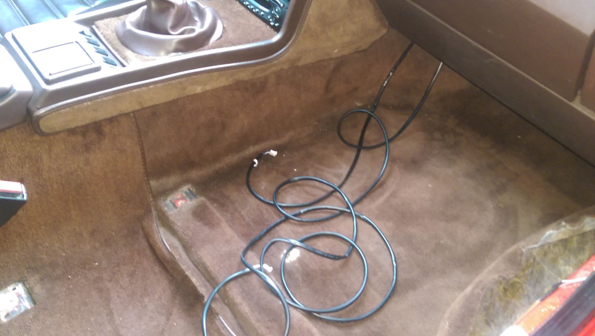
Mocked up the new harness and made branches just to see how it will lay. The nice thing about the NA engine bay is that the sensors are all in one area, so the harness won't be a tangled mess all over the place.
 06-13-2015, 03:37 PM