When you click on links to various merchants on this site and make a purchase, this can result in this site earning a commission. Affiliate programs and affiliations include, but are not limited to, the eBay Partner Network.
Wanted to update this thread: the linkage was great for months, but unfortunately last week the snap ring came out of the groove and a friend and I had to get under the car on the side of the road. I believe it boils down to the groove depth the McMaster-Carr snap ring is designed for versus what is actually machined on the 15mm shaft, I believe the groove needs to be a hair deeper. The reason it came out was because earlier that night my foot slipped off the clutch pedal during an upshift (wet shoes with little tread), so about 20 shifts later it let go and slid down the shaft.
Right now I'm on the fence about whether it's worth implementing a remedy, or just buying another linkage (used OEM with little play, or aftermarket). Right now I have a Schnell SSK installed which I had sitting around and to be honest I like the feel of the stock throw a lot more. The aluminum block that clamps to the trans stub also sketches me out... the set screw is installed correctly, but half of the bolt is hanging out because the aluminum part is half as thick as the stock linkage. There seem to be several accounts of that screw backing out.
So on the topic of rectifying the snap ring seat issue - would drilling a through-hole next to the ring land with a cotter pin be viable? Would serve the same function as safety wire on a bolt. Or maybe a spiral retaining ring instead of a snap ring? The real solution is to machine the ring land but I'm not going to bother.
My S/H pre-production model works very well, so far. I was quite impressed with how much nicer it was than the rusted up POCrap that I had in there. Big SHOUT OUT to Michael for this great product..IMHO.
My S/H pre-production model works very well, so far. I was quite impressed with how much nicer it was than the rusted up POCrap that I had in there. Big SHOUT OUT to Michael for this great product..IMHO.
and I'm honored that it went to a top-notch restoration! If you have issues with the snap ring, PM me and I'll take care of it.
Just to say Kyle's shifter is great. Improved the shift dramatically. I did fit a boot over the ball joint but I can see no problem with the aluminium, loctite and or wire it. It's far better than the one I had before at a fraction of the cost, very prompt service too.
i dont understand how everyone is just ok with the fact that all these aftermarket shifters except michael's is way too narrow on a critical dimension. loctite and safety wire be damned, its a design flaw.
If anyone wants detailed instructions for how to do this modification I'm happy to share detailed steps and a bill of materials. I know I was making these for a small profit earlier this year, but I no longer have time and plus it's a pretty simple procedure.
1) Disassemble linkage by removing the nut and the snap ring
2) Separate everything. The washer behind the snap ring gets stuck sometimes, a small puller helps. Be careful to keep the plating intact on the main 15mm shaft, that's corrosion protection
3) Thoroughly clean everything. I recommend a wire wheel on everything that exhibits corrosion. Also clean up the threads on the 10mm shaft if they're rusty.
3) Take as-found measurements of the plastic coupler (the part that connects the 2 metal pieces). You want to write down the dimensions across the faces where the shafts go through. The objective is to have a reference point, so that you mill these faces down the right amount to accept the bearings, while ending up with the original dimensions.
4) Look at your main shaft (the fore/aft 15mm one) at the point where it meets the back slotted plate. Imagine there's a bearings that rides there, right up against the back plate. Is the surface excessively pitted from corrosion, or do you think a needle thrust bearing would be ok to ride on it? This decision determines if you need to add a washer there, or not.
5) Measure the as-found dimensions of your bearings and washers. This is best to do as a sandwich...washer/bearing/washer. See 3D blowups on previous posts to determine placement and quantity. For each shaft direction, that's the amount you need to mill off the coupler to respect the original dimensions.
6) Using a method of your choice, mill the ledges off of the coupler - keep it square! Don't eyeball this or your shifter will have resistance at weird points.
7) Take measurements and determine how much you still have to mill off, so that after you add the bearing assemblies, you're on target. It should go without saying that you should keep the amount removed symmetrical to maintain geometry.
8) Measure often so you don't overshoot.
9) When you're close, test fit everything. Measurements are to get you in the ballpark, the final milling in the fore/aft direction should be determined by the location of the snap ring groove on the shaft. You want to be able to fully seat the ring and have very slight resistance as you turn the coupler around the shaft. I don't have a go/no-go measurement, but it should be snug without there being much friction.
10) Also ensure your 10mm (side/side) shaft is ok. Remember to re-use the washer up there, it sits on a ledge and has a weird ID. You could probably find a replacement but usually you don't need to.
11) Lube the bearings with grease (use your favorite) and install everything. Use a new snap ring - you can find the part # in the PET, I don't have it offhand but they're under a dollar I think. I used a McMaster Carr part and it came off after 6 months of shifts. Use a new lock nut obviously, with some blue loctite if you are so inclined. The ledge for the washer keeps the torque from crushing the coupler between the bearings, so if there's a ton of friction, you need to mill a little more until nothing is extended over that ledge.
Make sure it feels solid in your hands and nothing binds. If it does, back to milling! The end result should be tight and firm while still have free, but dampened, articulation.
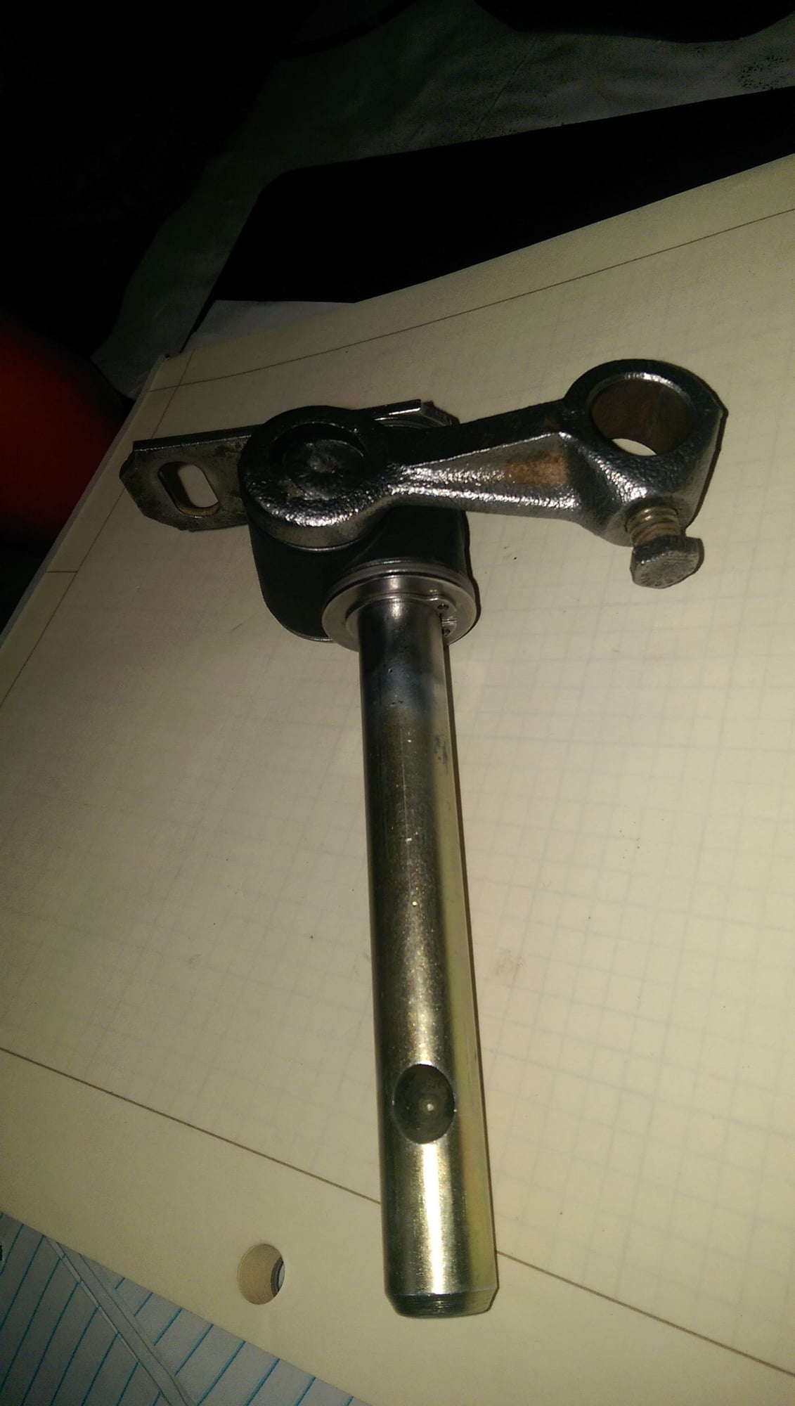
Here are some pictures of one I did. Note that for this one, I opted to use both washers for each of the bearings - otherwise the bearing elements would be rolling across a pitted surface. This is the recommended approach, unless your existing surfaces are very smooth or you otherwise don't care.
 08-27-2015, 12:49 PM