1983 Porsche 944 - Dirt Track Race Car Build
 11-12-2014, 01:41 AM
#31
Rennlist Member
Are you going racing at Merrittville Speedway? It's the only dirt track around here I know of.
I'm in central Ontario. My 944 has been around Barrie Speedway more than a few times.
I'm in central Ontario. My 944 has been around Barrie Speedway more than a few times.
 11-15-2014, 10:59 PM
#32
Track Day
Thread Starter

Join Date: Sep 2014
Location: Ontario, Canada
Posts: 15
Likes: 0
Received 0 Likes
on
0 Posts
Parawhore; The car is actually being built for Brighton Speedway. I doubt that I'll be traveling with it to any other tracks, but might be at some of them with the other guys at some point.
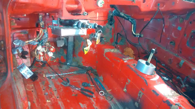
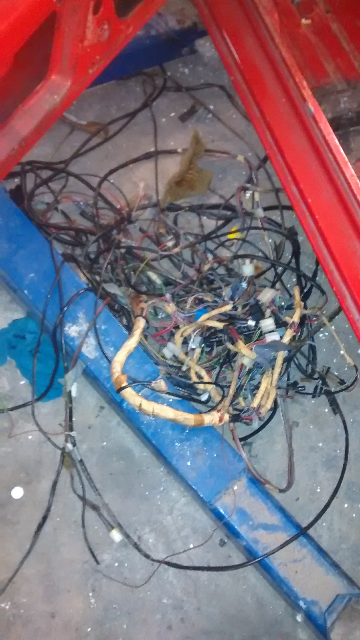
So I went about removing all the unnecessary wiring from the car. I started by identifying all the items in the fuse boxes and removed the plugs/fuses/relays that weren't needed, pulling out the associated wires as I went. I left the Fan and fuel pump/DME relay hooked up, as well as the fuel pump fuse.
Unfortunately it couldn't all go that smoothly and somehow in the mix I managed to remove the ignition wiring harness. This wouldn't be too much of a problem since I need to wire up a push button start panel anyways, but I'm now having trouble tracing some of the wires back to where they should be.
I'm no electrician but I am generally pretty good at 12v wiring. However, these German wiring diagrams from 1983 are getting the better of me in places. I can trace all the wires back and around for the most part, but was hoping I could get some clarification on what I'm getting hung up on.
The biggest part is identifying exactly what the numbering along the top of these diagrams means. They each show 30, 15, x, 31 and 50 (sometimes 58, etc). This is holding me up because, for example, when I trace back pin 50 on the ignition switch to plug E -pin 17, it says that this pin then goes to circuit number 50 in the relay board but without knowing what circuit 50 is, I am lost.
Van, you seem to have a good handle on the electrical side. Any input?
11-16-2014, 01:06 AM
#34
Track Day
Thread Starter
Join Date: Sep 2014
Location: Ontario, Canada
Posts: 15
Likes: 0
Received 0 Likes
on
0 Posts
I certainly have watched that video! I'm assuming you're the same Van? I've actually been subscribed to your channel for a while now. Great information you've got on there!
I'm actually slightly jealous of the 85.5+ wiring diagrams. They may be a bit more complex but the layout seems much more logical and easier to follow.
For future reference (anyone that may come across this thread in the future looking for answers to a similar problem), I believe the numbers at the top of pre-85.5 wiring diagrams are as follows;
30 = +12V Constant
15 = +12V On ignition and with starter activated
X = +12V On ignition but not with starter activated
31 = Ground
50 = +12v Only when starter is activated
My "incident" with the removal of the ignition harness may have been a bit bigger problem than I first thought.
From what I can see in the diagrams though, I should be able to hook the ignition toggle switch to send 12v to the DME relay which will power the DME itself (and in turn, the fuel pump). Then the starter can be hooked to the momentary push button switch with an extra wire powered on activation to send a signal to pin 4 on the DME and let it know that it's cranking.
Just have to figure which pin on the DME relay activate it and which send power to the DME and I should be set.
Hopefully that's it and I haven't accidentally removed any other necessary wires that I haven't noticed yet!
11-16-2014, 10:49 AM
#35
Rennlist Member
I'm going on memory here, but there are 2 power leads to the DME - pins 18 and 35 on the DME plug (which went to the brake booster plug - a white square plug with 9 pins on the early cars). Both of these should be powered up with the toggle switch.
The push-button starter signal also has to go to DME plug pin 4.
And then DME plug pin 20 is the ground signal to "close the circuit" for the 2nd half of the DME relay - the part that triggers the fuel pump.
On my car, even though it's a late car, I just used 2 relays - one which is positive switched to send power to the DME; and one that is negative switched from the DME for the fuel pump.
I've also done an early car where I used toggle switches for both the DME and fuel pump, but I'm not as comfortable with that... in the event of a crash, if the engine shuts off, the fuel pump will still be running.
I don't know if I posted this before, but here's my car's fuse block. The small fuse block is always on, and when the "ignition" toggle switch is flipped, it just activates that unlabeled relay which powers up the larger terminal block. This way my cool shirt, radiator fan, aux power (video camera), etc. will work while I'm in staging with the engine off.
11-24-2014, 12:22 AM
#36
Track Day
Thread Starter
Join Date: Sep 2014
Location: Ontario, Canada
Posts: 15
Likes: 0
Received 0 Likes
on
0 Posts
Thanks again Van, your information is invaluable (as are the pictures of your setup). I received my ignition panel and decided to throw together a mock-up so I'll be able to reference it when I am doing the wiring. I've simplified it a bit more from yours. Everything powered in the car is set to turn on/off with the ignition switch as nothing needs to be powered when the car is off.
The only slight downfall is that there are a bunch of fuses now in lines that were previously unfused, so I will have to figure out proper amperage ratings to use for these.
The only question I have left about this is if I need to power the ignition coil off the switch as well? It appears that you have yours set to receive power with the switch but I didn't see any wires from the original ignition switch connecting to the coil in the factory wiring diagrams (although I know it's fed off switched power).
Anyways, I've attached my own slightly messy schematic. If you notice any errors or ways that it can be improved I would be happy to hear them.
11-24-2014, 10:31 AM
#37
Rennlist Member
First, I don't think you need fuses to the fuel pump relay and fuel pump power feed to the the relay... since you have a fuse *after* the relay, too.
Second, just make sure your power wire coming out of the relay is stout enough to handle the lights, fuel pump and DME together without an appreciable voltage drop - you want the DME to be running 100%.
I assume aux lights includes brake lights?
Will you have a radiator fan?
I'd think you can put the coil and fuel injectors on the same fuse.
11-24-2014, 01:07 PM
#38
Track Day
Thread Starter
Join Date: Sep 2014
Location: Ontario, Canada
Posts: 15
Likes: 0
Received 0 Likes
on
0 Posts
Yup, there is a radiator fan but I didn't include it in the diagram since I am manually activating it on it's own circuit.
You're right about the unnecessary extra fuses though. I originally did it that way because I thought it would make the wiring cleaner but it's probably just as easy to run a wire off the unfused terminal on the fuse block.
I had originally drawn this out by hand and labelled the wires with gauge thicknesses as well but didn't transfer those when I made the digital copy. My plan was to run 10 gauge wire from the output on the DME relay but I can always run a separate power wire for the fuel pump if there is any voltage drop.
As far as brake lights, we don't run them. So "aux. lighting" is actually just a single running light in the standard third brake light location.
I'll add the coil wiring and make a few changes. Then as soon as my fuse block arrives it will get wired up!
11-25-2014, 07:42 PM
#39
Hates Family Guy
Rennlist Member
Rennlist Member
Found another on Craigslist - http://wausau.craigslist.org/cto/4734096910.html
I was talking to a local wrench, and he said there used to be another one running the dirt track just north of here, in Fountain City, WI.
I was talking to a local wrench, and he said there used to be another one running the dirt track just north of here, in Fountain City, WI.
 12-25-2014, 10:50 PM
#41
Track Day
Thread Starter
Join Date: Sep 2014
Location: Ontario, Canada
Posts: 15
Likes: 0
Received 0 Likes
on
0 Posts
Just thought I'd add a little Christmas update to show what I've been up to lately with the dirt 944. I've put the rest of the wiring on hold for a bit until I get a dash made so I won't have to route it more than once. (Sorry in advance for the size of the pictures!) Since the last update I have;
Pulled the front hubs and had them re-drilled to the standard 5x5 bolt pattern, including larger wheel studs and 1" steel lug nuts. Paired the new hubs with some steel Aero Race Wheels. (Still have to get the rear hubs re-done to match)


Next I pulled the transmission so I can crack it open and weld the differential (Don't worry, I know this isn't a recommended modification for street cars, or even regular race cars but it is absolutely essential for a dirt track car). As you can see, the transmission is absolutely caked in grease, undercoating and dirt. Since this picture it has undergone a serious degreasing and pressure wash, I just haven't had a chance to take any more pictures of it since. The gas tank was also removed to make room for the fuel cell that will be replacing it.


Next I removed the doors and broke out the plasma cutter to start gutting them. This is both for weight savings and more importantly, to make room for Nascar-style door bars (which are required by our rules). As you can see by the pictures, they're fairly barren but I left the double layer of steel around the window frame to retain some rigidity during the re-install. However, they are still heavier than you would think by looking at them, so they may get trimmed down even more still.


And finally; the most recent work done was starting on the roll cage, which will continue sometime in the next week. So far we've gotten the main hoop and halo done. I'm quite pleased with how it's looking so far. Since the 944 has a rather tight driver space, we put my racing seat in the car and I then got in while wearing my racing helmet prior to starting on the cage. We tested clearance between my head and all the bars first and maximized the space as best we could. Next on the list are the A-Pillar and door bars, followed by all the other braces.


And finally, just a little race car **** of the other car that's been taking up our time! Merry Christmas everyone!

Pulled the front hubs and had them re-drilled to the standard 5x5 bolt pattern, including larger wheel studs and 1" steel lug nuts. Paired the new hubs with some steel Aero Race Wheels. (Still have to get the rear hubs re-done to match)
Next I pulled the transmission so I can crack it open and weld the differential (Don't worry, I know this isn't a recommended modification for street cars, or even regular race cars but it is absolutely essential for a dirt track car). As you can see, the transmission is absolutely caked in grease, undercoating and dirt. Since this picture it has undergone a serious degreasing and pressure wash, I just haven't had a chance to take any more pictures of it since. The gas tank was also removed to make room for the fuel cell that will be replacing it.
Next I removed the doors and broke out the plasma cutter to start gutting them. This is both for weight savings and more importantly, to make room for Nascar-style door bars (which are required by our rules). As you can see by the pictures, they're fairly barren but I left the double layer of steel around the window frame to retain some rigidity during the re-install. However, they are still heavier than you would think by looking at them, so they may get trimmed down even more still.
And finally; the most recent work done was starting on the roll cage, which will continue sometime in the next week. So far we've gotten the main hoop and halo done. I'm quite pleased with how it's looking so far. Since the 944 has a rather tight driver space, we put my racing seat in the car and I then got in while wearing my racing helmet prior to starting on the cage. We tested clearance between my head and all the bars first and maximized the space as best we could. Next on the list are the A-Pillar and door bars, followed by all the other braces.
And finally, just a little race car **** of the other car that's been taking up our time! Merry Christmas everyone!

