
12v constant for stereo "battery" connection: EDIT TO ADD PIC
 11-19-2005, 08:12 PM
#1
Resistance is Futile
Lifetime Rennlist
Member
Lifetime Rennlist
Member
Thread Starter
Cutting to the chase here, the PO had a bastardized headunit install and I am splicing back in an original harness for a connection point to a modern breakout harness.
I was left with two bundles of wires from the harness points, one for the speakers, etc and one grouping of 5 wires.
Here's the million dollar question, where do you get 12v constant for the "radio memory" and what is the exact color of the wire?
Thanks in advance... I've spent hours scouring the electrical sections of the shop manuals here and either I am completely missing it or something just isn't adding up.
Thanks,
75ohm.
Last edited by 75ohm; 11-28-2005 at 06:04 PM. Reason: Issue Resolved
 11-21-2005, 11:55 AM
#2
Resistance is Futile
Lifetime Rennlist
Member
Lifetime Rennlist
Member
Thread Starter
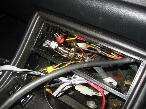
Need some help folks... attaching picture to clarify...
All I had was the two bundles of wires, one for the speakers, one with 5 wires, two identified, need help with the other three. I have checked all fuses and am using a multimeter with no luck.
Thanks,
75ohm.

All I had was the two bundles of wires, one for the speakers, one with 5 wires, two identified, need help with the other three. I have checked all fuses and am using a multimeter with no luck.
Thanks,
75ohm.
11-21-2005, 12:10 PM
#3

Just run a wire from the positive battery terminal to the unit, cut it and put a fuse and an be done with it. Odds are the factory is the black and red. It should show 12V constant on the wire however.
__________________
Best Car Insurance | Auto Protection Today | FREE Trade-In Quote
__________________
Best Car Insurance | Auto Protection Today | FREE Trade-In Quote
11-21-2005, 12:18 PM
#4
Nordschleife Master
I know how much of a nightmare it is to fix the wire harness, the previous owner of my car did a real hack job. Took me forever to fix.
This is what i went by when i did the radio on my '87
brown - ground
red (thick wire)- 12v switched power
red with white stripe (maybe orange? - radio dimmer
red - power antenna
green - 12v constant
On your car i see you have two brown wires, i would think those are either the radio dimmer, power antenna or maybe something to do with the radio fader switch.
The speaker wires...
yellow - left driver rear
white - left driver door
red - right passenger door
black - left passenger rear
This is the joy i found when i pulled the PO's aftermarket Blaupunkt.
Good luck!
11-21-2005, 12:23 PM
#5
Resistance is Futile
Lifetime Rennlist
Member
Lifetime Rennlist
Member
Thread Starter
Will hit when I get home tonight and check it out. I know I could always run a wire to the battery, but to me, it's defeatist to do so!  Keep you all posted and thanks for taking the time.
Keep you all posted and thanks for taking the time.
11-21-2005, 01:44 PM
#7
Resistance is Futile
Lifetime Rennlist
Member
Lifetime Rennlist
Member
Thread Starter
Tifosiman - check the pic, I have the following available:
Brown - ground
Green with white stripe - 12 v switched from ignition
Red - not identified
smaller wires:
brown w/black stripe
light brown
Brown - ground
Green with white stripe - 12 v switched from ignition
Red - not identified
smaller wires:
brown w/black stripe
light brown
Trending Topics
11-21-2005, 02:46 PM
#10
Race Car
The six-pin connector commonly used in mid-80s has two large pins and four smaller ones:
Pin 1) Brown - Ground (large pin)
Pin 2) Red - 12v switched power input (large pin)
Pin 3) 12v illumination power input (from pin 4)
Pin 4) 12v radio-switched output (to pin 3)
Pin 5) 12v radio-switched output (to power antenna)
Pin 6) Permanent 12v input (to maintain memory)
A second set of power connectors are provided for the optional equalizer/amplifier:
Brown - Ground
Red/white - Permanent 12v power
Red/black - 12v when radio is switched on
11-21-2005, 02:53 PM
#11
Three Wheelin'
Join Date: Sep 2002
Location: Austin, TX
Posts: 1,283
Likes: 0
Received 0 Likes
on
0 Posts
The six-pin connector commonly used in mid-80s has two large pins and four smaller ones:
* Pin 1) Brown - Ground (large pin)
* Pin 2) Red - 12v switched power input (large pin)
* Pin 3) 12v illumination power input (from pin 4)
* Pin 4) 12v radio-switched output (to pin 3)
* Pin 5) 12v radio-switched output (to power antenna)
* Pin 6) Permanent 12v input (to maintain memory)
A second set of power connectors are provided for the optional equalizer/amplifier:
* Brown - Ground
* Red/white - Permanent 12v power
* Red/black - 12v when radio is switched on
The schematic in the Haynes manual for speaker wires is incorrect for later cars. The color codes used for the various speakers are:
* Left Front - White
* Right Front - Black
* Left Rear - Yellow
* Right Rear - Red
Taken from 944 Stereo FAQ. Carefully read the wiring list for your deck and this. My Alpine had a thicker wire that goes to the thicker Red/White wire, then a thinner one that was for switched 12 volt, to tell it to turn on when the ignition is on.
I follows that speaker color code list and it worked in my car. The wire with the solid color should be the positive and the one with the color and the stripe should be ground IIRC.
http://944faq.986.org/KevinGross/Electrical/Stereo.htm
This was taken from a post by 'theedge' in 2003. I think I remember when wiring my 944's stereo the green was the constant power...
11-21-2005, 03:01 PM
#12
Resistance is Futile
Lifetime Rennlist
Member
Lifetime Rennlist
Member
Thread Starter
Michaelathome, thanks for the info. I have that information as well; however, recall in thread that I started with no harness at all. I am splicing back in an original harness (done for speakers and switched power/ground no problem) but the pin 6 wire isn't happy. I also have the aftermarket installation kit from crutchfield so that I "breakout" from there...
11-21-2005, 03:06 PM
#13
Resistance is Futile
Lifetime Rennlist
Member
Lifetime Rennlist
Member
Thread Starter
Robert D, thanks for the info - I read the 944faq backwards and forwards as well. If I bond the 12v constant and 12v battery together for the feed, all is fine. Speakers are fine as well. I am entrenched with knowing where the 12v constant is and what the 3 remaining wires are for!!!
11-21-2005, 03:13 PM
#14
Race Director
Originally Posted by 75ohm
You have a PM.