930 waste gate plumbing?
#17
Resurrecting this thread as I am dealing with a similar issue. Does anyone have a simple diagram showing what the wastegate plumbing should like on an original 930? It wasn't clear to me on the previous diagrams on this thread if any of them were showing the original setup/components?
#18
Rennlist Member
The diagram Peter uploaded in post 13 is close to the OE set up.
On the diagram, follow the "6mm supply line" from the IM plenum [from the intercooler on the OE system] toward the waste gate. If you remove the small control line going to, and leaving, the "manual air regulator", and remove the regulator, the diagram would be representative of the OE system.
Note: intercooler not shown in diagram.
#19
The diagram Peter uploaded in post 13 is close to the OE set up.
On the diagram, follow the "6mm supply line" from the IM plenum [from the intercooler on the OE system] toward the waste gate. If you remove the small control line going to, and leaving, the "manual air regulator", and remove the regulator, the diagram would be representative of the OE system.
Note: intercooler not shown in diagram.
On the diagram, follow the "6mm supply line" from the IM plenum [from the intercooler on the OE system] toward the waste gate. If you remove the small control line going to, and leaving, the "manual air regulator", and remove the regulator, the diagram would be representative of the OE system.
Note: intercooler not shown in diagram.
#20
Rennlist Member
There are three ports on the intercooler...one on the left side and two on the right side.
The one on the left provides a pressure signal to the waste gate. One on the right is capped off, and the other goes to the AAR.
The one on the left provides a pressure signal to the waste gate. One on the right is capped off, and the other goes to the AAR.
#21
The previous owner made so many "mods" and added lots of pretty red and yellow tubing (some which goes nowhere!) that it's difficult for me to tell if I have any components replaced or missing.
#22
Rennlist Member
You would probably get better results by posting center-left, on-center, and center-right photos of your motor here, and let folks peruse over its current configuration.
#23
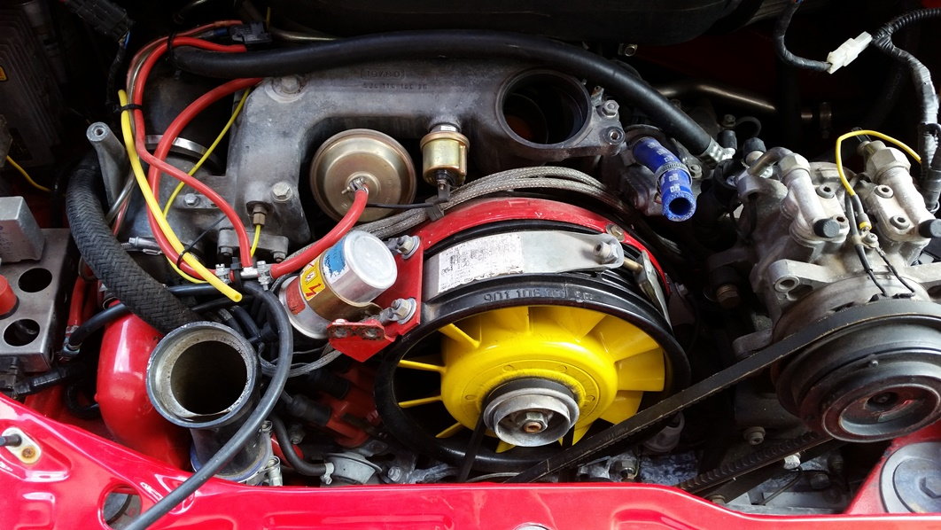
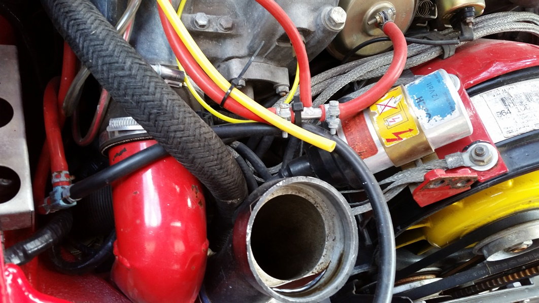
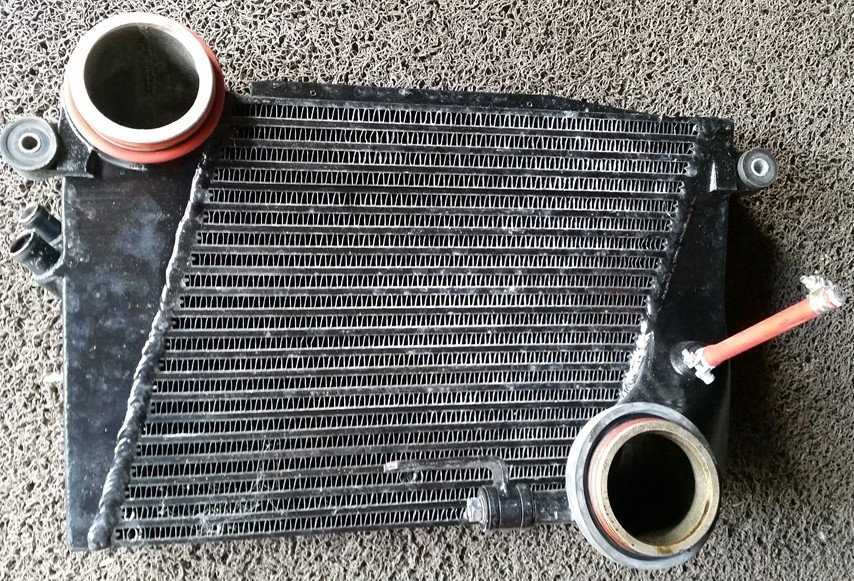
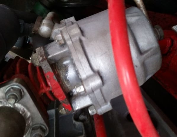
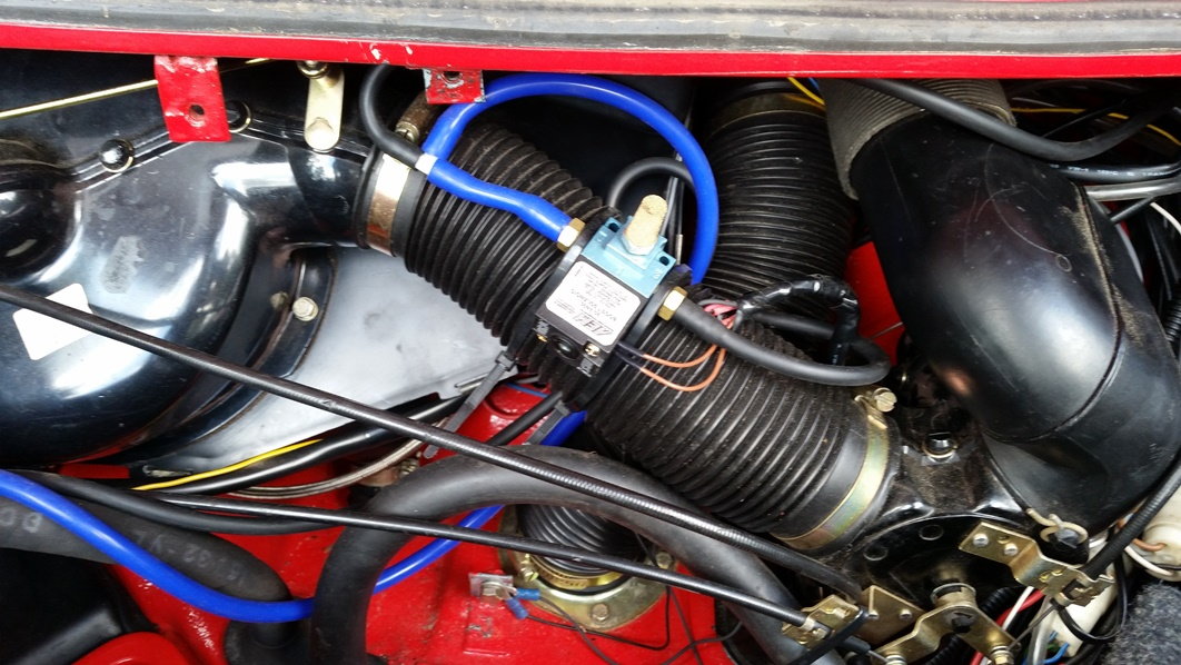
#24
Rennlist Member
K27...not stock. OE was a KKK 3LDZ.
AEM...not stock [I would toss that in the waste bin]. OE boost controller was simply a spring in the waste gate. How much boost is your motor running...15 lbs?
From the photos, you still have the factory: 1) compressor bypass valve assembly [large cast aluminum housing] between the fan shroud and air box, 2) vacuum limiter [60mm circular part with attached red vac hose between shroud and CBV housing], 3) boost pressure sender [to right of vacuum limiter attached to CBV housing], 4) aux air regulator [to right of CBV housing with attached blue vac hose], 5) ignition coil, 6) turbo compressor discharge up pipe [to left of distributer cap], 7) intercooler, and 8) waste gate.
If you don't like the red/blue vac hose, you can still find black, cloth-braided, hose to un-bling the engine compartment.
#25
Yes already done that with glee, never trust those buggers, Motronic is the only way to do that properly from my past experiences (968 Turbo RS) but not intending to go down that path with this.
From the photos, you still have the factory: 1) compressor bypass valve assembly [large cast aluminum housing] between the fan shroud and air box, 2) vacuum limiter [60mm circular part with attached red vac hose between shroud and CBV housing], 3) boost pressure sender [to right of vacuum limiter attached to CBV housing], 4) aux air regulator [to right of CBV housing with attached blue vac hose], 5) ignition coil, 6) turbo compressor discharge up pipe [to left of distributer cap], 7) intercooler, and 8) waste gate.

#26
Rennlist Member
More boost [>15 psi] + stock intercooler + stock headers ---> lean AFR and/or detonation. Have you removed all manual boost control? So, the waste gate spring is the only mechanism controlling boost pressure?
Until you get this car on a dyno to verify AFR throughout the rev range at full boost, I would be very careful with the go pedal.
The rest of the engine compartment looks mostly stock, save for the colorful vacuum lines and what appears to be the boost controller piping.
#27
This would worry me...a bit.
More boost [>15 psi] + stock intercooler + stock headers ---> lean AFR and/or detonation. Have you removed all manual boost control? So, the waste gate spring is the only mechanism controlling boost pressure?
Until you get this car on a dyno to verify AFR throughout the rev range at full boost, I would be very careful with the go pedal.
The rest of the engine compartment looks mostly stock, save for the colorful vacuum lines and what appears to be the boost controller piping.
#28
Rennlist Member
You've taken the manual boost controller out of the equation...and the boost gauge still climbs past 1 bar?
Is the vacuum hose from the left side of the intercooler connected to the side port of the waste gate? If not, that could be the problem. If so, then someone has either replaced the OE waste gate spring with a stiffer one [e.g. 1.0 bar or 1.2 bar] or shimmed it to increase its resistance.
Is the vacuum hose from the left side of the intercooler connected to the side port of the waste gate? If not, that could be the problem. If so, then someone has either replaced the OE waste gate spring with a stiffer one [e.g. 1.0 bar or 1.2 bar] or shimmed it to increase its resistance.


